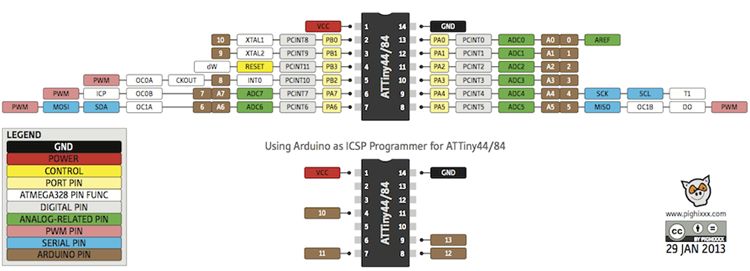
My order of ATTiny84 chips from Mouser arrived yesterday, so it is time to load the Arduino Blink example sketch onto it. I made a small line follower using the ATTiny85 a while back, and quite liked the idea of having a smaller, cheaper IC that can run simpler Arduino sketches. The ATTiny84 comes with extra 6 I/O pins (see datasheet), so it should be an even better replacement of an Arduino for smaller projects. Here is a beautifully rendered mapping of the ATTiny84 / ATTiny44 pins courtesy of Alberto (PighiXXX):
UPDATE, June 24th, 2015: The article below was written for Arduino IDE versions, prior to 1.6.4. If you are currently using Arduino IDE 1.6.4, or later, follow the instructions in blog post instead.
I use my Arduino Uno to program the ATTiny84 via the SPI. Here are the basic steps:
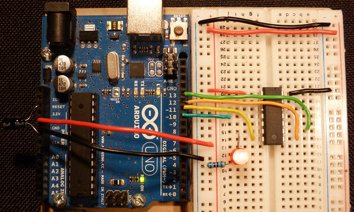
- Step 1: Collect all necessary hardware components:
You will need an Arduino Uno, the ATTIny84/44 IC you want to program, an LED to test the Blink sketch, a 470 Ohm, or similar current limiting resistor for the LED, a breadboard and some jumper wires. - Step 2: Add an ATTiny support (core) to the Arduino Uno IDE
- Step 3: Configure the Arduino Uno to act as an a ATTiny programmer
- Step 4: Wire the ATTiny84 / ATTiny85 to the Arduino Uno
- Step 5: Upload the Blink Sketch and make sure everything works correctly
- Step 6: Set up the ATTiny84 to work at 8Mhz for better compatibility with Arduino Libraries.
Steps 1 to 3 are exactly the same as in the ATTiny85 Programming tutorial that I posted earlier.
The connections between the ATTiny84 / ATTIny44 and the Arduino Uno for Step 4 are as follows:
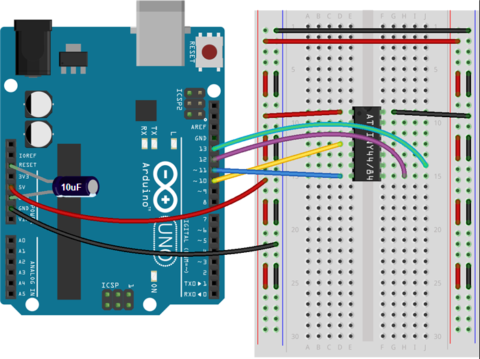
- Connect a 10 uF capacitor between “Reset” and “Ground” pins on the Arduino Uno board as shown in the diagram. The stripe of the capacitor with the negative sign (“-”) goes to the Arduino “Ground” pin. This prevents the Arduino Uno from resetting and ensures that the Arduino IDE talks to the ArduinoISP (and not the bootloader) during the upload of the sketches to the ATTiny.
- Connect the ATtiny84/44 Pin 1 (with the little dot) to the 5 volt breadboard rail.
- Connect the ATtiny84/44 Pin 14 to ground.
- RESET: Connect the ATtiny84/44 Pin 4 (Reset) to Arduino Pin 10.
- MOSI: Connect the ATtiny84/44 Pin 7 to Arduino Pin 11.
- MISO: Connect the ATtiny84/44 Pin 8 to Arduino Pin 12.
- CLOCK: Connect the ATTiny84/44 Pin 9 to Arduino Pin 13
- Connect the ground and 5v from the Arduino to the breadboard.
A minor change needs to be made to the default Blink example sketch, as the ATTIny84 / ATTiny44 do not have pin 13. I use pin 7 and connected an LED to it and to ground via a current limit resistor (470 Ohm) . The wiring diagram and updated sketch are below. Note that the numbering of the Attiny84 pins in the datasheet does not necessarily match the Arduino mappings. Pin 6 on the ATTiny84, for example, is actually Arduino digital pin 7 (see pinout diagram at the beginning of the post).
/*
  Blink (modified slightly for ATTiny84/44 ICs
  Turns on an LED on for one second, then off for one second, repeatedly.

  This example code is in the public domain.
 */

// ATTIny84 / 44 does not have Pin 13, so we use pin 7 instead.
// A current limiting resistor should be connected in line with the LED.
int led = 7;

// the setup routine runs once when you press reset:
void setup() {
  // initialize the digital pin as an output.
  pinMode(led, OUTPUT);
}

// the loop routine runs over and over again forever:
void loop() {
  digitalWrite(led, HIGH);   // turn the LED on (HIGH is the voltage level)
  delay(1000);               // wait for a second
  digitalWrite(led, LOW);    // turn the LED off by making the voltage LOW
  delay(1000);               // wait for a second
}
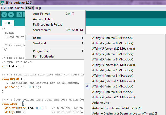
Make sure you select the option “ATTiny84 (internal 1 MHz clock)”, or “ATTiny44 (internal 1 MHz clock)” in the Tools->Board menu (depending on which version of the chip you have):
Upload the sketch using the “File” -> “Upload Using Programmer” command (Ctrl + Shift + U).
If you get an error like this: “avrdude: please define PAGEL and BS2 signals in the configuration file…”, you can safely ignore it. This relate to parallel programmers and is not an issue here.
If all works well, you should have a blinking LED and a proven method for uploading Arduino sketches to your ATTiny84/44. Congratulations!
The next step (Step 6) is optional. By default, the ATTiny chips run at 1 MHz. You need an extra step to configure the microcontroller to run at 8 MHz. This is a requirement for using some popular Arduino libraries, as well as to take full advantage of your chip.
To do so, you need to use the same wiring that you used to upload the blink sketch in the previous step. Under “Tools”->”Board” menu, this time select the option “ATtiny84 (internal 8 Mhz clock)”, or “ATtiny44 (internal 8 Mhz clock)”, depending on which chip you have. It is important to pick the correct clock speed from the menu. Choosing the 20 Mhz external clock option, will require you to add wire in a 20 MHz crystal, or resonator, in order to program and use your ATTiny84/44.
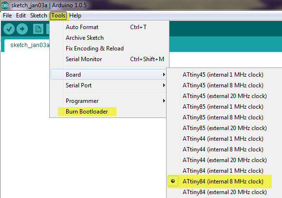
Next, again under the “Tools” menu, choose the option “Burn Bootloader”. There is actually, no bootloader on the ATTiny chips, but this step will set the fuses to the values that will allow it to run at 8 Mhz, similarly to what we did for the ATtiny85 in the previous write-up.
Again, ignore any errors related to PAGEL and BS2 signals you may get. To make sure the change worked, you may want to re-upload the modified Blink sketch from step 5, this time using the internal 8 MHz clock option for your chip from the Boards menu.
Next, time to use the ATTiny in a real project! A warning: not all Arduino libraries will work on the ATTiny chips. The Arduino forum is a great place to search for additional info, if you run into issues. Chances are, someone already had this problem and found a solution.
Comments
Comment by Gabriele on 2014-03-18 10:55:16 -0700
HI i have a question, when I select the option “ATtiny84 (internal 8 Mhz clock)” the Attiny runs to 8Mhz or you must also change the internal fuses?
Se seleziono the option “ATtiny84 (external 20 Mhz clock)” devo costruire un circuito esterno con due condensatori da 22pf e un cristallo. Invece di usare un cristallo da 20Mhz posso usare un cristallo 16Mhz e usare la stessa opzione(ATtiny84 (external 20 Mhz clock) quando scrivo il bootloader?
Comment by Stan on 2014-03-18 14:02:44 -0700
Hi Gabrielle,
you can change the default frequency of the ATTIny chip from 1 to 8, or 20Mhz following the instructions in step 6. When you do that, the fuses will be set for the frequency you have selected from the “Board” menu. No extra steps are required.
On your second question: I am not sure that using a 16Mhz crystal with fuse settings expecting a 20Mhz one will work. Maybe the good folks at the Arduino forums will be able to help you…All I can say from my limited experience is that messing around with the fuse settings without good understanding of what you are doing can easily lead to “bricking” your ATTiny…
I hope you figure it out, and please post back if / when you do!
Stan
Comment by juanmol on 2014-08-13 01:51:56 -0700
Hi, i’ve test with attiny85 and works, but if i try with attiny84, the led is not blinking. I’ve check all and is correct, the output messages in arduino ide are the same with attiny85 (and working). I ‘ve remove all my arduino libraries and binaries, download again, and get the same result. Of course i have test with a few attiny84. Can you help me?
Comment by Sergio on 2016-06-05 15:27:42 -0700
Hi.
I’m developing a flashlight using this attiny for my bike. I would like to add more LEDs (everything is better with more LEDs) but I’m not sure if I can use the pins related to the programming interface.
Can I attach blinking LEDs to mosi, miso and clock and still be able to reprogram the attiny? I’m afraid of…I don’t know, destroy my programmer or “dissipate” the program sent to the LEDs connected to the arduino instead of programming it.
Thanks for your help!!
Comment by Kurt Barcelona on 2017-02-26 14:55:51 -0700
pin7 in the code is on pin10 of the AtTiny84A. the diagram has a wrong pin mapping for arduino
Comment by Erik on 2017-08-05 17:31:44 -0700
What If I have one that I would like to make a copy of? IS there a way to successfully copy and ATTINY44?
Comment by Steve Johnson on 2018-05-19 18:30:02 -0700
Yes! I just did this – I used pins 7, 6, and 5 as PWM outputs (might be useful for you to adjust the brightness of your LED lamp), and the Arduino Uno programmer uses pin 7(MOSI) as a programming pin. I wired an RGB LED in to those pins on the programming shield I made. I compiled and uploaded the program using the Arduino IDE, it completed, and started the program, driving the RGB LED as I had hoped. I haven’t tried this using pin 8 (MISO), which is also connected to the Arduino UNO.