As part of a project to make DIY water activated diving flashing marker, I needed a simple circuit to detect when the marker is in contact with water. Turns all all it takes to do that is a a couple of basic components. Here is the diagram; P1 and P2 are the probes that will be in contact with water:
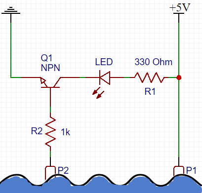
The LED (and its current limiting resistor) can be replaced with a buzzer circuit, a micro-controller, or another “smart” component to notify you of the water presence.
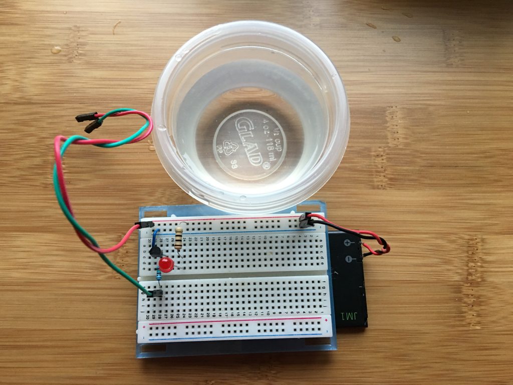
For my purposes it will connect to a 555 timer circuit that will control the duty cycle and on-off times of the flashing marker to maximize battery life. The whole circuit, including a coin cell battery will be encased with epoxy, to allow it to function underwater, during dives, so minimizing current draw, while ensuring the LED is still visible underwater is key. Below is my breadboard prototype:
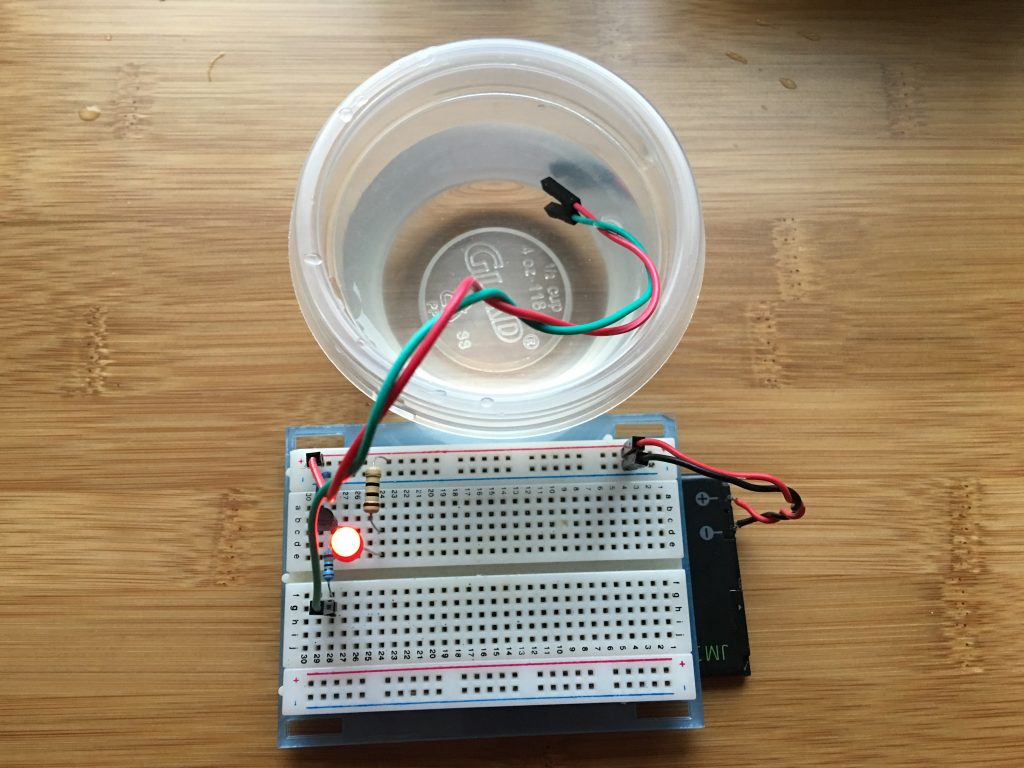
Probes in contact with water and the LED is on, it works!
It is important to note that pure (distilled) water is not a good conductor and this circuit may not work so well. It works fine with tap water and even better in salty water (where I will be using the diving flasher).
The 1K R2 resistor is there to protect the NPN transistor, in case the two contacts (P1 and P2) are connected by something more conductive than water.
Comments
Comment by Jordi on 2019-10-18 01:38:26 -0700
Hi,
Have you finished the diving marker with the 555? Could you please share the final diagram?
thanks,