ATTiny Line Follower
Continuing to mess around with the ATTiny85 IC… I ported the code from my Arduino Uno line following robot to the ATTiny. Some changes were necessary to make it work:
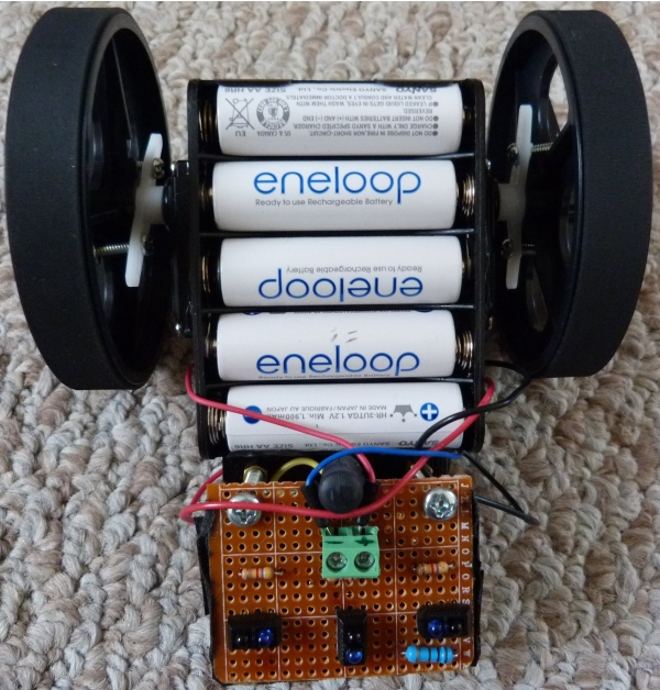
- The ATTiny has only 3 analog pins, so the sensor array has 3 TCRT5000 IR LED/Sensors instead of the 6 the original line follower had
- The SoftwareServo library was needed, as the standard servo library that comes with the Arduino IDE does not work on the ATTiny
The code used is below, and more info on how to program the ATTiny chip using your Arduino as a programmer is available in this post. There is one more pin available on the ATTiny85, so I am thinking of adding an ultrasound sensor and some basic obstacle avoidance next. Here is the Arduino Code that runs on the ATTiny:
#include <SoftwareServo.h>

SoftwareServo LServo; //create servo object for the left servo
SoftwareServo RServo; //create servo object for the right servo

const int maxSpeed = 180; // the range for continuous rotation servos is (0,180)

/* Define the pins for the IR sensors */
const int irPins[3] = {A1, A2, A3};

/* Define values for the IR Sensor readings */
int irSensorDigital[3] = {0, 0, 0};

int treashold = 600; // IR sensor treashold value for line detection

// binary representation of the sensor reading
// 1 when the sensor detects the line, 0 otherwise
int irSensors = B000;

// A score to determine deviation from the line [-180 ; +180].
// Negative means the robot is left of the line.
int error = 0;

int errorLast = 0;  //  store the last value of error

/* variables to keep track of current speed of motors */
int leftServoSpeed = 90;
int rightServoSpeed = 90;

void setup()
{
  LServo.attach(1); // attaches the left servo to pin 1
  RServo.attach(0); // attaches the right servo to pin 0
}

void loop()
{
 Scan();
 UpdateDirection();
 Drive(leftServoSpeed, rightServoSpeed);
 SoftwareServo::refresh();
}

void Scan() {
  // Initialize the sensors
    irSensors = B000;

  for (int i = 0; i < 3; i++) {
      int sensorValue = analogRead(irPins[i]);
      if (sensorValue >= treashold) {
        irSensorDigital[i] = 1;
      }

    else {
      irSensorDigital[i] = 0;
    }

    int b = 2-i;
    irSensors = irSensors + (irSensorDigital[i]<<b);
    }
}

void UpdateDirection() {

  errorLast = error;

  switch (irSensors) {

    case B000: // no sensor detects the line
       if (errorLast < 0) { error = -120;}
       else if (errorLast > 0) {error = 120;}
       break;

     case B100: // left sensor on the line
       error = -70;
       break;

     case B110:
       error = -40;
       break;

     case B010:
       error = 0;
       break;

     case B011:
       error = 40;
       break;

     case B001: // right sensor on the line
       error = 70;
       break;

     case B111:
       error = 0;
       break;

     default:
       error = errorLast;
  }

    if (error >= 0) {
      leftServoSpeed = maxSpeed;
      rightServoSpeed = maxSpeed - error;
    }

    else if (error < 0) {
      leftServoSpeed = maxSpeed + error;
      rightServoSpeed = maxSpeed;
    }
}

void Drive(int leftSpeed, int rightSpeed) {

    int left = leftSpeed;
    int right = maxSpeed - rightSpeed;
    /* This is due to servo positioning
       right servo needs to rotate back
       when the robot goes forward
    */

    // ensure input is in the correct range for servo control
    if (left < 0) {left = 0;}
    else if (left > maxSpeed) {left = maxSpeed;}

    if (right < 0) {right = 0;}
    else if (right > maxSpeed) {right = maxSpeed;}

    LServo.write(left);
    RServo.write(right);
}
And here is the “underbelly of the beast”. Messy wires everywhere…

0 Comments on “ATTiny Line Follower”