Experimenting with Sound Localization and Arduino
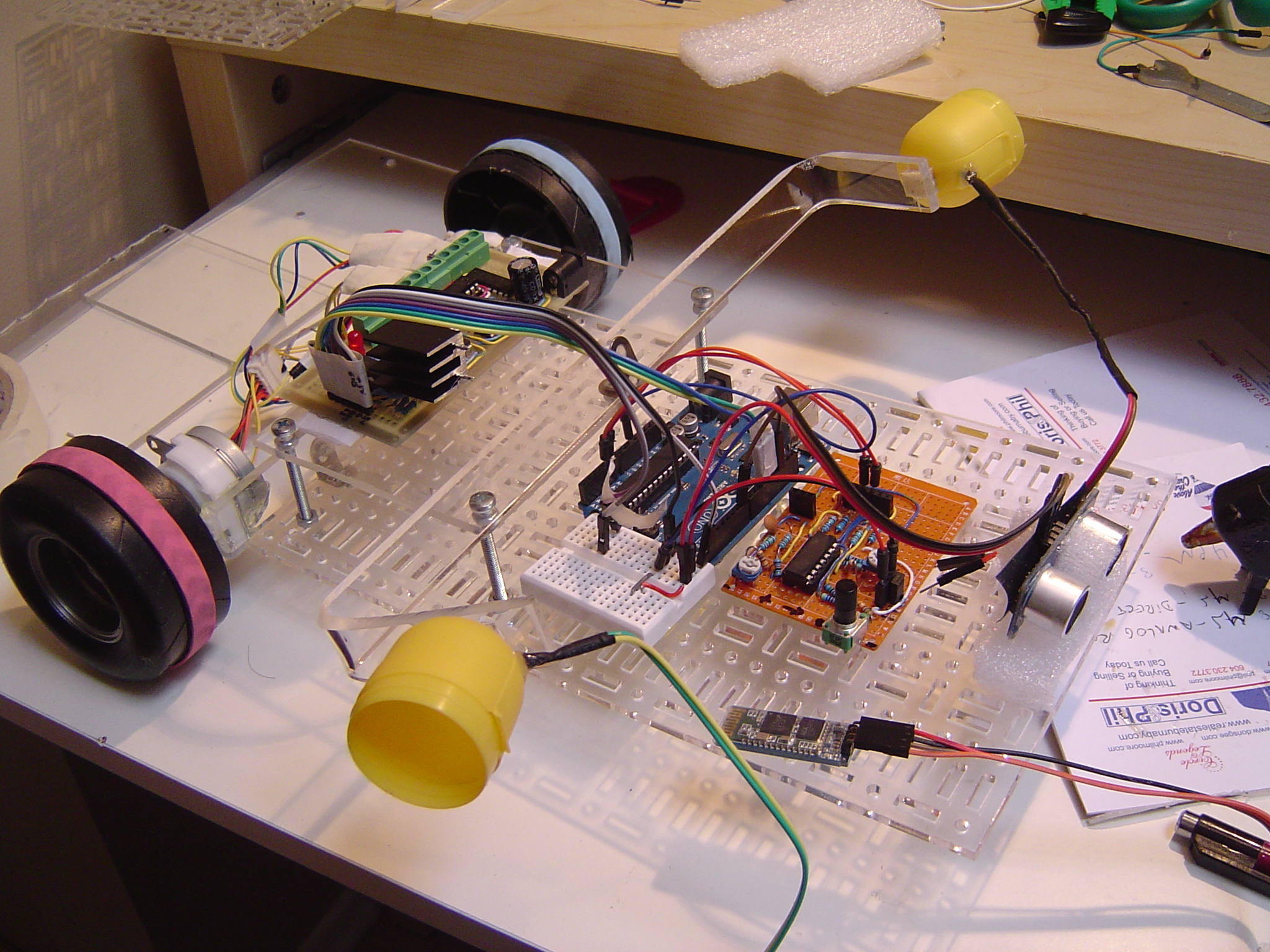
Today I’m going to walk you through my experience trying to localize the source of a sound using Arduino. My goal with this was to add a feature to my robot that would make it more interactive and look more “alive”.
Beta 1
What you normally see people doing, as an easy approach, is to measure the volume level from two microphones in which the amplified output is connected to the Arduino analog inputs. Whichever input is higher determines the source direction of the sound.
On the practical side this proves to be not that useful as it requires a huge amount of sound isolation between the 2 microphones, or the sound source to be extremely close to one of the microphones in order to give a reliable reading.
Also, what you get is normally a binary result “Left or Right” and I was looking for something a bit more precise, giving me an angle to the sound source.
Not being a scientist I had no idea of what I was getting into! Sound is a really sneaky thing and that’s what I enjoyed the most in doing this project. The simple realization that sound is formed by waves of energy that can bounce or be channeled in different ways depending on the materials opens you up for a greater understanding of all the challenges involved.
The hardware
For this project, as you may have guessed, you will need microphones. If you look around you’ll notice that you have microphones everywhere. The broken cellphone, that computer headset, etc.. Just try and get similar ones for your project as you’ll want readings to be consistent on all inputs. Online they cost US$0.25 (25 cents). Definitely not a show stopper.
Microphones are nothing more than sensors (transducers) that will convert the sound waves into an electric signal. Given the amount of energy in a sound wave and the microphone’s capacity what you get is an extremely low signal that would not be enough (<20mV) to provide a reading from the Arduino.
We need an amplifier that could bring that input to a level that generates meaningful values from the Arduino ADC (Analog to Digital Converter).
I used an Operational Amplifier IC (LM324) to amplify the signal. Don’t get scared, those are all cheap components.
Below, an excellent video explaining Operational Amplifiers and how to build the amplifier circuit I used.
Reading further about sound amplification, if that’s your only porpuse, an LM386 would produce better sound quality. For the purposes of this project all we need is an amplified signal, sound fidelity is not that important. LM324 worked just fine.
This is my amplification module
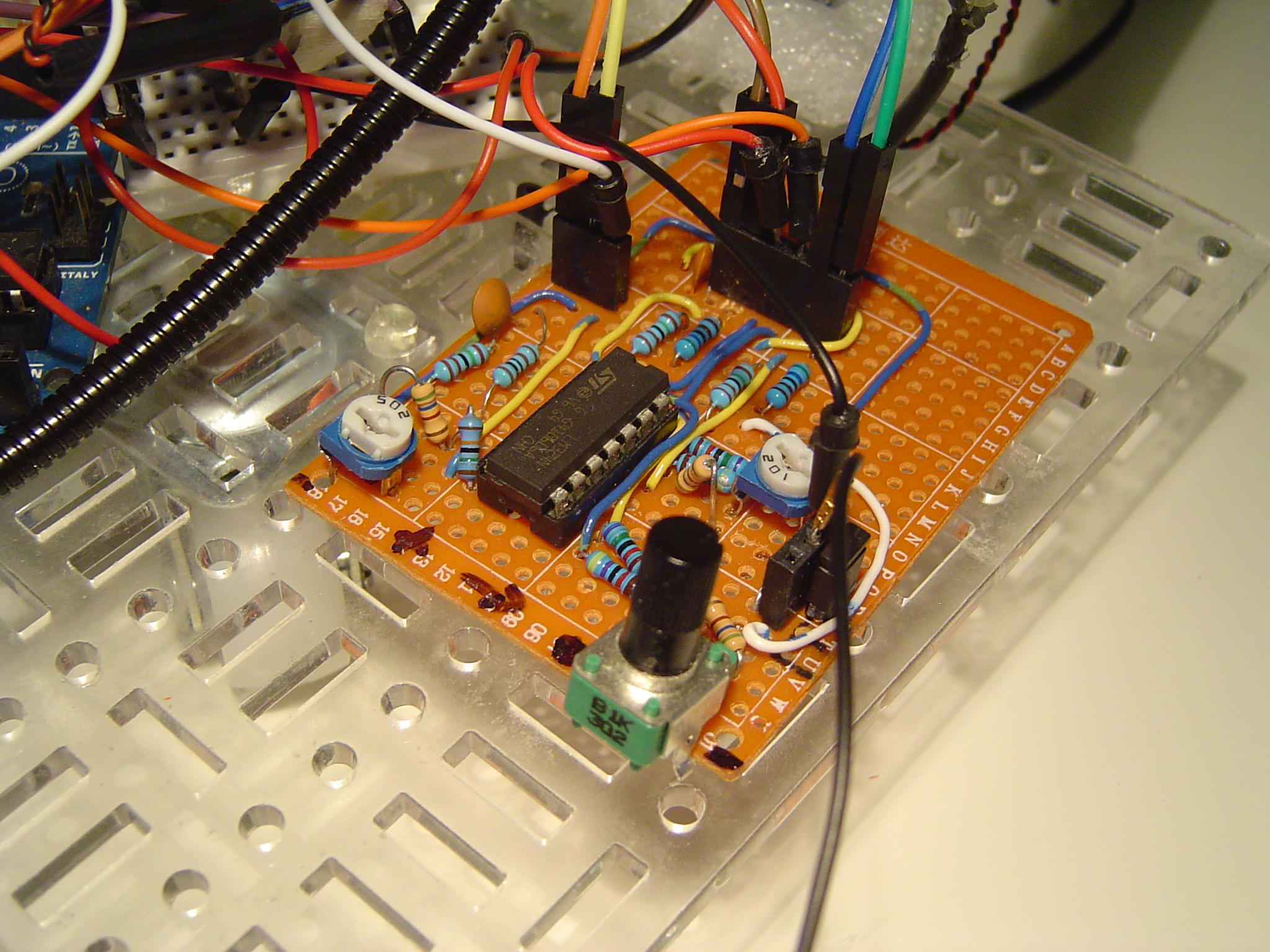
Note that I added potentiometers so I can have a finer control over the gain in each microphone. Note also that my module can have up to 3 microphones as inputs.
Each microphone has an output header that can be connected directly to the Arduino analog inputs.
Arduino
Knowing that just reading the output levels in 2 two microphones to determine direction would not be enough, my approach was to determine how long it took for the sound to reach each microphone, whichever sensor is triggered first defines the side (left/right) and the time difference or phase shift between the 2 microphones would allow me to triangulate the sound source… at least that was the theory.
Amplified output from 2 microphones in the oscilloscope.
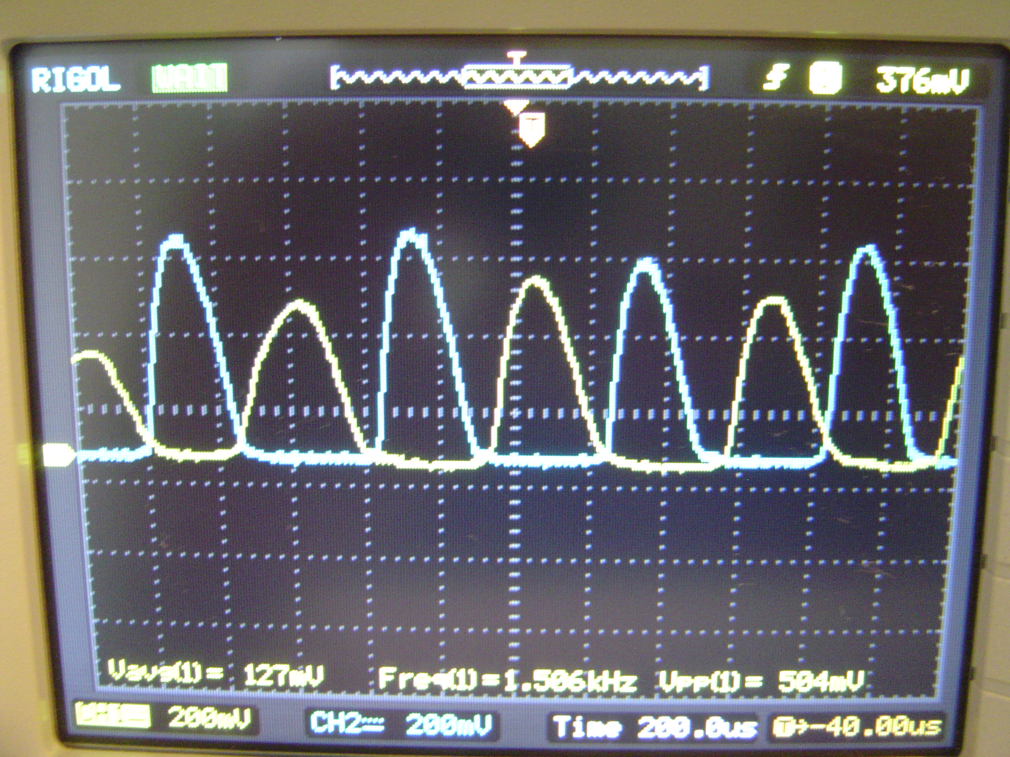
The time difference between the beginning of the waves in the 2 channels should allow for triangulation considering the speed of sound.
In my initial experiments, my “lab” was located in the laundry and, guess what? Saturday is laundry day and it happens to be the best day I have to play with electronics. My Arduino input was all over the place with the sound of the washing machine and drier generating all sorts of input values.
Arduino is an excellent platform but I wouldn’t try to code anything like voice recognition or a filter to isolate the sounds I was interested into. I needed something simpler that would be easy to identify given the hardware resources and program space.
I decided that my trigger would be a whistle.
If you look at the oscilloscope screenshot above, it is showing the waves produced by a whistle. The advantages of a whistle are that they can be loud enough to overpower other sound sources and can also provide a frequency that is easy to identify and be reproduced by a human.
My whistle produces a sound wave around 1.6Khz and that can be pretty distinct from normal noise. That, combined with some circuitry to implement a High Pass filter can help so we can dismiss undesired noises/frequencies.
What we have to do now is to capture that wave as readings from the Arduino ADC. Based on the wave pattern we should be able to identify the whistle (a sound wave that repeats itself 1600 times every second) and using 2 microphones how long it took for the same wave to hit both microphones (phase delay).
In the screenshot above you can see only half of the sound wave and that’s because in my amplifier module I’m not feeding a negative voltage. The Arduino ADC would just clip off any negative readings returning zero. That should not affect the results we are looking for.
Having a 1.6Khz input signal means that a complete wave will have passed an specific point (in this case our microphones) every 625 microseconds(us). Using the Arduino analogRead() function, assuming that’s all we do in the program, would take roughly 130us for each analog input read and that would reduce significantly the ability to determine the actual time difference in which a single wave hit the two microphones.
At that speed, using 2 microphones would allow less than 3 readings per cycle and would yield very imprecise results. I needed to speed up the Arduino ADC readings.
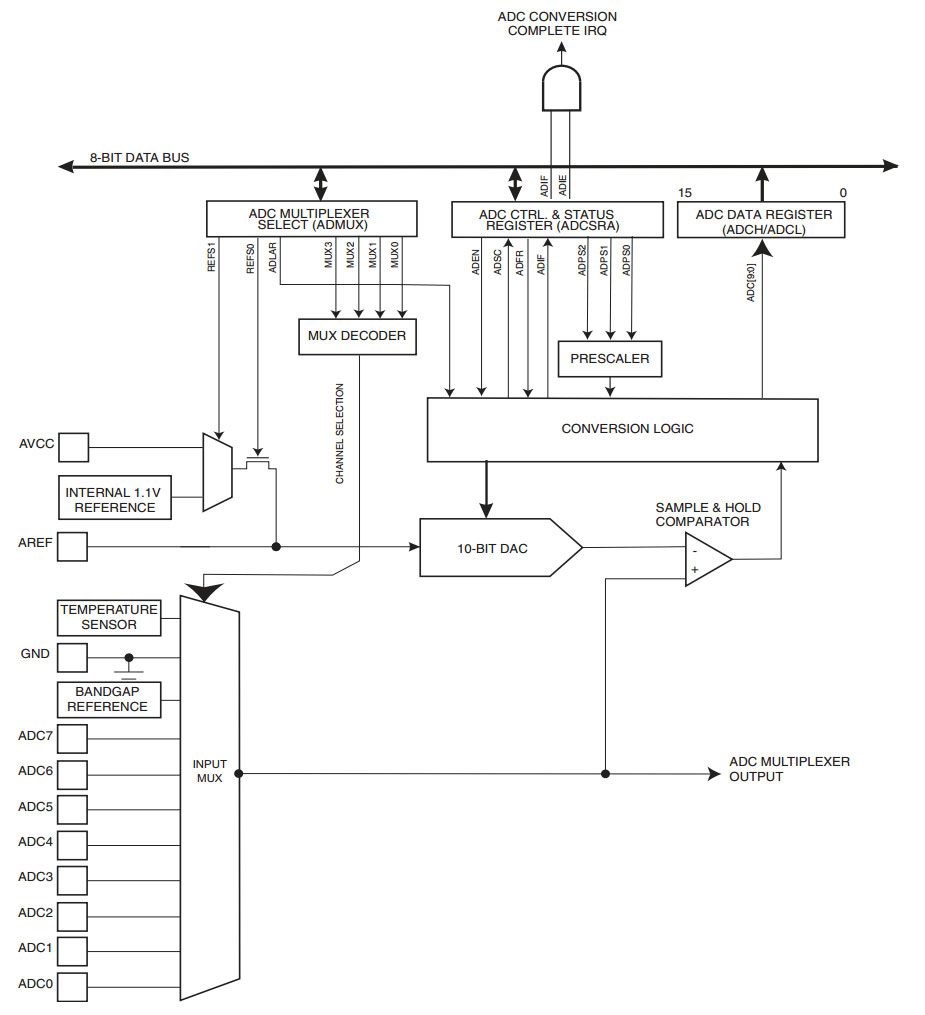
The Arduino ADC is a successive approximation circuit that requires a certain time to process a sample reading. It gives at the end of the conversion a 10 bit number (0-1023) which should be proportional to where the input voltage is in relation to ground and the reference voltage.
If we are willing to sacrifice resolution we can increase the frequency of readings changing the Arduino prescaler associated to the ADC, and instructing the chip to fill only 8 bits.
Be aware that when you start messing around with chip registers you are taking in your hands a lot of the hard work the Arduino platform do for you. For instance, the Arduino exposes 6 Analog input pins but the ATMEGA chip itself has only one ADC circuit. In order to enable you as a user to simply refer to an analog port by the number, the IDE will do all the multiplexing work required to hook up the port you want to the ADC circuit and wait for the results. This all has now to be done manually as shown in the code below and that renders all other analog inputs useless, except the one being addressed, during the time this sketch is running. This does not damage your Arduino, everything goes back to normal when you load a new sketch.
The ATMEL datasheet has all that information but it may be a bit difficult to understand it at first glance. This post is also a great reference.
ATMEGA328 ADC schematics
The code below shows all the settings to change the Arduino prescaler, perform the multiplexing and hook up an interrupt so the code can proceed during an analog conversion.
It is not intended for you to simply cut/paste and have it all working out of the box as, for instance, I save the latest 50 readings in an array that is not declared in the excerpt below.
I’ll explain more after you take a look.
void setADCA0()

{

cli();//disable interrupts
//clear ADCSRA and ADCSRB registers
ADCSRA = 0;
ADCSRB = 0;
ADMUX |= (1 << REFS0); //set reference voltage
ADMUX |= (1 << ADLAR); //left align the ADC value- so we can read highest 8 bits from ADCH register only
// Sets to Analog 0
ADMUX &= 0xF2;// VRef=VCC/Left adjust result/Analog 0
ADCSRA |= (1 << ADPS2); // 16 prescaler
//ADCSRA |= (1 << ADPS2) | (1 << ADPS0); //set ADC clock with 32 prescaler- 16mHz/32=500kHz
ADCSRA |= (1 << ADIE); //enable interrupts when measurement complete
// — ADCSRA |= (1 << ADATE); //enabble auto trigger
ADCSRA |= (1 << ADEN); //enable ADC
ADCSRA |= (1 << ADSC); //start ADC measurements // ADSC goes to 0 after conversion is complete // ADIF = 1 When data registers are updated sei();//enable interrupts } ISR(ADC_vect) {// When new ADC value ready // —— if (!match) { tRead = micros(); // Multiplexes ADC switch (ADMUX) // only bytes related to analog pin selected { case 96: // Analog 0 // Save previous reading to detect falling or rising edge levelROld = levelR; levelR = ADCH>noiseTol?ADCH:0;
ADMUX = B01100010; //0xF2; // Next select Analog 2
aLevelR[j] = levelR;
aTime[j] = tRead;
// Detect start of the wave
if (levelR > 0 and levelROld == 0)
{
if (iR<2) // If iL==2 this wave capture is completed, waiting for the other side { aStartR[iR] = aTime[j]; aStartVR[iR] = levelR; } } else if (aStartL[iR] > 0 ) // Beginning of the wave was detected in some point
{
if (iR==0 )
{
if (levelR==0) // Checking for 0 ensures it’s a new wave (negative side) and not pure noise or falling edge.
{
iR=1;
aStartR[1] = 0;
aStartVR[1] = 0;
}
}
else
{
iR = 2;
}
}
break;
case 97: // Analog 1
// Save previous reading to detect falling or rising edge
levelLOld = levelL;
levelL = ADCH>noiseTol?ADCH:0;
aLevelL[j] = levelL;
ADMUX = B01100000; //0xF0; // Select Analog 0
// Detect start of wave only if left or right are set
if (levelL > 0 and levelLOld == 0)
{
if (iL<2) // If iL==2 this wave capture is completed, waiting for the other side { aStartL[iL] = aTime[j]; aStartVL[iL] = levelL; } } else if (aStartL[iL] > 0 ) // Rising edge and peak was detected in some point
{
if (iL==0 )
{
if (levelL==0) // Checking for 0 ensures it’s a new wave (negative side) and not pure noise or falling edge.
{
iL=1;
aStartL[1] = 0;
aStartVL[1] = 0;
}
}
else
{
iL = 2;
}
}
j++;
if (j>48)
{
j = 0;
}
break;
case 98: // Analog 2
// Save previous reading to detect falling or rising edge
levelCOld = levelC;
levelC = ADCH>noiseTol?ADCH:0;
aLevelC[j] = levelC;
ADMUX = B01100001; //0xF0; // Select Analog 1
// Detect start of wave only if left or right are set
if (aStartL[iL]>0||aStartR[iR]>0)
{
if (levelC > 0 and levelCOld == 0)
{
if (iC<2) // If iL==2 this wave capture is completed, waiting for the other side { aStartC[iC] = aTime[j]; aStartVC[iC] = levelC; } } else if (aStartC[iC] > 0 ) // Rising edge and peak was detected in some point
{
if (iC==0 )
{
if (levelC==0) // Checking for 0 ensures it’s a new wave (negative side) and not pure noise or falling edge.
{
iC=1;
aStartC[1] = 0;
aStartVC[1] = 0;
}
}
else
{
iC = 2;
}
}
}
break;
}
// Verify if the waves correspond to the desired frequency
if (iL==2&&iR==2)
{
if (abs(aStartL[0] – aStartR[0]) < trgPrd/2 + tolPrd) // Check if the 3 waves were captured in sequence { // Frequency check if ((aStartR[1] – aStartR[0] >= trgPrd – tolPrd)&&(aStartR[1] – aStartR[0] <= trgPrd + tolPrd)) { if ((aStartL[1] – aStartL[0] >= trgPrd – tolPrd)&&(aStartL[1] – aStartL[0] <= trgPrd + tolPrd)) { readMore ++; if (readMore>20) // Capture a bit more of incoming sound
{
readMore = 0;
match = true;
}
}
}
}
if (!match)
{
reset();
}
}
}
if (!match)
{
ADCSRA |= (1 << ADSC); //start ADC measurements
}
}
As you may have noticed I ended up implementing 3 microphones as sometimes I was unable to determine which microphone was hit first. It could be that the very first wave was not captured by one of the microphones, for whatever reason, and that would yield a wrong determination of the source side.
The third (central) microphone gives me a reference as it is slightly closer to the left (L) microphone than the right (R) one.
Also, the code will consider a valid reading only when the frequency seems to be around 1.6Khz. Because 3 analog readings would consume over 90us, I had to add a tolerance value to consider a reading valid based on frequency.

In the picture above you see the disposition of the microphones. The logic is to store the last 50 readings (analog reading and time in microseconds) until I hit the desired frequency.
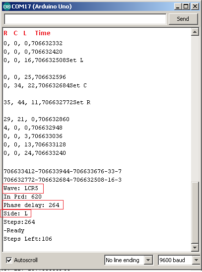
When the frequency is a match I start going through the array looking for the beginning of a wave in the left microphone as a starting point, from there I store the order in which the waves showed up in C and R.
If I get the sequence L-C-R it means the wave came from the left, if I get L-R-C it means the wave came from the right. There’s a whole bunch of exceptions to this logic specially if the source is closer to front center but I think that gives you the idea.
Having L and R mics 10 centimeters apart ensures that I’m dealing with the same wave as it would take 291us for the sound wave to go that distance (the whole wave lasts around 600us). I took 343m/s as the speed of sound here.
Sample readings
There’s still a long way to go to get this right, the logic will not work specially close to walls and I suspect it is because of bouncing waves. Not sure how deep I want to go with this but I’m quite happy with what I learned for the time being.
Please comment if you have a better way of doing any part here. It seems a cool feature to add to any robot.
hello
That is amazing project and you done well.
My graduation project is this but I have some trouble about microfone and amplifie the signal .
Can you send me a your circuit of microfone please .
I really need help .
Thank your interest.
ow///4 or 5 canal lm324n?
Can you send me the full code for me ?
This project is in progress. It is struggling to progress. Help us appreciate
can you explain more about the sequence L-C-R OR L-R-C? and what will be the sequence if the wave hit the center mic first.
In that case L and R will be hit almost at the same time which means the sound came straight from the front.
but the three mics are in the form of a triangle, and the method you are saying is used when there is two mics.
what you say about the eq.- time difference between two mics= distance between two mics*sin angle/speed of sound.
any further research or articles posted ?
Hi
i know its an old thread, but have you had any progress on that ?
I am very interested in the project.
Nick
hello, awesome project, I like it! Can you send me a full code of this project?