Differential drive with continuous rotation servos and Arduino
Purpose:
Create a simple and easy to control drive system for a small robot with minimal number of parts and connections.
Parts list:
- 2 Servos modified for continuous rotation
- Arduino Uno
- Wires
- Caster (s) / skid (s)
- Some sort of robot base and wheels
- Zip ties, or hot glue and hot glue gun
Theory of operation
Differential Drive
Differential drive is a very popular drive system for small robots. It is easy to build, control and allows the robot to move in all directions. Two drive wheels are attached at the right and at the left of the robot’s base, each connected to a motor. Those two motors are responsible for moving the robot and for steering. This system even allows a robot to pivot in its place, around the center point between the two wheels. One or two casters / skids are used, depending on the construction of the base and the robot’s center of gravity.
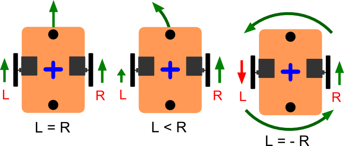
The diagram below illustrates the principle of operation of differential drive:

- When the two wheels are spinning in the same direction and the same speed, the robot will move straight.
- When the two wheels are spinning in the same direction, but with different speeds, the robot will turn away from the faster motor. For example, if the right wheel is spinning faster than the left, the motor will turn left.
- If the two wheels are spinning with the same speed, but in opposite directions, the robot will rotate in place, spinning around the midpoint between the two wheels.
The name (“differential steering”) comes from the way the robot is steered by changing the speed and direction (“difference”) between the two wheels.
Continuous rotation servos
Continuous rotation servos are a modified version of the standard servos (those that you can set to a specific position, usually between 0 and 180 degrees). If you remove the geared feedback to the internal pot in the servo and also remove the mechanical end stops on the gear train, you end up with a variable speed, bi-directional geared motor that you can drive with a single Arduino pin. The downside of this modification is that you can no-longer move the servo to a specific position. You can control the direction of rotation and the speed only.
Due to the ease of use of servos, some manufacturers started producing and offering these factory modified for continuous rotation. So, there are two ways to get continuous rotation servos:
- Buy a standard servo and modify it for continuous rotation yourself. This may take some practice and patience, but it is not hard. I have done that with some small servos.
- Buy a servo manufactured for continuous rotation. I got mine from Solarbotics, but you can buy them from many hobby electronics and robotics stores ( SparkFun, Adafruit, Parallax, eBay, Amazon, etc.).
Putting it all together
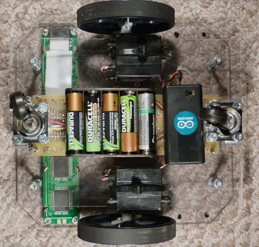
Mounting the servos to the robot base
The servos should be mirrored horizontally, so the output shafts are aligned. If you bought a pre-designed robot kit, the chassis may come with mounting wholes and brackets that fit well together.
If not, the simplest way to mount your servos in a cheap DIY project is with hot glue. If you need a stronger, more reliable bond, you can drill some holes in the base, just outside of the servo body outline and strap it down with a couple of zip ties. This should be more than enough for most small robots.
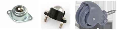
Casters / Skids Configuration
Casters, free rotating wheels and skids are added to the base to keep the robot level. You can purchase casters suitable for small robots from numerous places online, use wheels salvaged from old furniture, or use your imagination and make skids from wires, ping pong balls etc…
Depending on the positioning of the wheels and the robot’s center of gravity, you may need one or two casters.
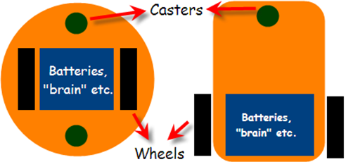
A robot will respond better to steering commands and will be more stable, if most of its weight falls in the area between the two wheels (the blue square area in the diagram above). A low center of gravity helps as well.
Wiring
Continuous rotation servos have the same connections as the standard servos: power, ground, and signal.
The power wire is typically red, and should be connected to a 5V power supply (check the the rating of the servo, some can be run at 6V for additional speed and torque). Servos can draw considerable power, so you should power them from a separate power supply (i.e. not the +5V pin on your Arduino).
The ground wire is typically black or brown and should be connected to a common ground with the Arduino board.
The signal wire is typically yellow, orange or white and should be connected to a digital pin on the Arduino board.
For the example code below, I have the signal wires from the servos connected to pins 2 and 4 on an Arduino Uno (you do not need to use a PWM enabled pin, any digital pin will do).
Arduino Code
The sample Arduino code below can be used to drive a robot using two continuous rotation servos and differential steering. The signal pin of the two servos are connected to the Arduino Uno digital pins 2 and 4 (respectively). A reminder: servos should be powered by a separate regulated power supply.
The code includes a “drive” function that takes two parameters: the speed for each servo (from 0 to 180). Putting the servo code in a dedicated function is not required, but helps to keep the code in the loop easier to read. This will be especially useful, when you add more complex behavior to your robot and need to process inputs from multiple sensors within the loop function.
Note that due to the way the servos are mounted (mirrored horizontally across the chassis middle) you need to send “0” to one and “180” to the other, to get the wheels rotating in the same direction. This can be confusing, so the best way is to try it out.
/********************************************************************
Differential steering with continuous rotation servos and Arduino Uno
Version: 1.0
Date: January 2014
Author: Stan
Web-Site: http://42bots.com/
********************************************************************/
#include <Servo.h>

Servo LeftServo;
Servo RightServo;

// the control signal for the left servo
const int leftServoPin = 2;

// the control signal for the right servo
const int rightServoPin = 4;

void setup()
{
   LeftServo.attach(leftServoPin);
   RightServo.attach(rightServoPin);
}

void loop()
{
   //Drive forward for 3 seconds
   Drive(180, 0);
   delay(3000);

   //Drive in reverse for 3 seconds
   Drive(0, 180);
   delay(3000);

   //Rotate counterclockwise for 3 seconds
   Drive(0, 0);
   delay(3000);

   //Rotate clockwise for 3 seconds
   Drive(180, 180);
   delay(3000);
}
/*
Drive function. Sample calls:
 - (180, 0) for full forward
 - (0,180) for full reverse
 - (90, 90) for stop

Servos are mirrored on the chassis.
*/
void Drive(int leftServoSpeed, int rightServoSpeed) {

  if (leftServoSpeed < 0) {leftServoSpeed = 0;}
  else if (leftServoSpeed > 180) {leftServoSpeed = 180;}

  if (rightServoSpeed < 0) {rightServoSpeed = 0;}
  else if (rightServoSpeed > 180) {rightServoSpeed = 180;}

  //Send the command to the servos
  LeftServo.write(leftServoSpeed);
  RightServo.write(rightServoSpeed);
}
Of course, there is more than one way to do things, so time to experiment with your set-up!
Aweeeeaome you are a great resource for beginners like me!!! Muchas gracias!!!
Glad you found the post useful, Juan, and thanks for your comment!
Thank You for the helpfull shared references 🙂
Hi. I want to make a robot with Arduino and have a 2WD with it controlled via 433Mhz radio reciever transmitter pair. Can you please give me a sample code for such a robot?
Hi Stan,
Great tutorial, quite useful! I am a newbie to arduino and building robots, so kindly excuse silly questions.
Do we also need a Motor Shield for Arduino, for this project? I did not see one mentioned in the parts list in the tutorial.
Thanks,
Tejanshu