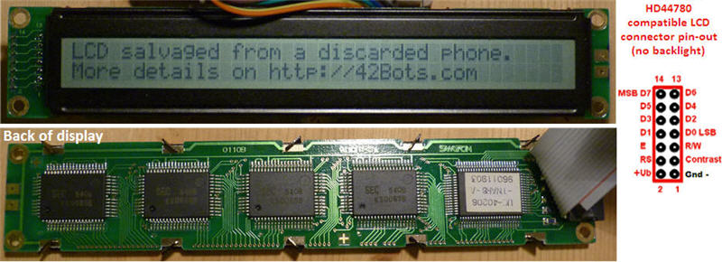
A couple of days ago I came across a discarded Meridian PBX phone and naturally, took it apart. Among some of the more promising salvaged components was a 40 x 2 character LCD. There was a ribbon cable attached to the LCD with a 14 pin female connector. The pins were helpfully labeled on the front of the panel (from 1 to 14). On the back of the LCD I could see five KS00065B LCD Driver chips.
The next thing to find out was how to hook this up to my Arduino Uno.
The
LiquidCryslal Arduino library seemed like the place to start, but its description specifically mentioned that it works with LCDs based on the Hitachi HD44780 driver. The standard 14 pin female header on my LCD was a good sign. After some poking around on the Internets, I confirmed that the drivers at the back of my “new” LCD were indeed compatible with the Hitachi one.
This type of LCDs will have 14, or 16 pins, with pins 1-14 used to power and communicate with the LCD and pins 15 and 16 powering the optional backlight. You will need to have a current limiting resistor between the 5v rail and pin 15 of the LCD. The value of that resistor depends on the the maximum backlight current and the typical backlight voltage drop, which should be listed in the LCD datasheet. Most LCDs with a backlight will already include a current limiting resistor in series, but make sure you confirm that before hooking it up. My LCD had only 14 pins, so no backlight to worry about.
Here is a description of the LCD pin functions:
- Ground
- VCC (+3.3 to +5V)
- Contrast adjustment (Analog, Voltage range 0-Vcc, Highest contrast at 0)
- Register Select (RS). RS=0: Command transaction, RS=1: Data transaction
- Read/Write (R/W). R/W=0: Write, R/W=1: Read
- Clock (Enable). It is set to high to begin writing an instruction and then to low to finish writing.
- Digital I/O pin (Not used in 4-bit operation mode)
- Digital I/O pin (Not used in 4-bit operation mode)
- Digital I/O pin (Not used in 4-bit operation mode)
- Digital I/O pin (Not used in 4-bit operation mode)
- Digital I/O pin
- Digital I/O pin
- Digital I/O pin
- Digital I/O pin
- Backlight Anode (+).
- Backlight Cathode (-)
The first three pins provide power to the LCD module. Pin 1 is GND and should be grounded to the power supply. Pin 2 is VCC and should be connected to +5V power. By changing the voltage or duty cycle of pin 3, the contrast of the display can be adjusted. I connected a 10K Ohm trimpot, to be able to adjust the contrast manually. Most character LCDs can achieve good display contrast with a voltage between 5V and 0V on pin 3. To my surprise, greater contrast comes with lower voltage and you should never apply a voltage higher than VCC.
Pins 4, 5 and 6 are the control lines for the LCD. These lines indicate what kind of instructions are going to be sent over the data lines (pins 7-14).
Character LCD modules are accessed through two “registers”, the Command Register, and the Data Register. When you perform a read or write with RS (pin 4) set to low, you are accessing the Command Register and giving the LCD module commands like “Clear Display”, “Set Cursor Position” etc. When you write with the RS pin set to high, you are accessing the Data Register and writing characters/data to be displayed on screen.
The R/W line (pin 5) indicates whether you intend to read from registers (high) or write to the registers (low). To save a pin on my Arduino, I connected the R/W pin to ground (essentially keeping it in write mode all the time). The downside is that I will not be able to read from the LCD this way, but hey you can’t have it all!
Pin 6, the Clock (Enable) line, tells the display when you are actually ready to perform the instructions. It is initially set to “high” to begin writing the transactions to the registry and then (after a small delay to allow for the LCD to accept the data that is sent) set back to “low” to finish the writing cycle.
The control lines RS, R/W, and E, along with the data lines (pins 7 to 14) are standard digital logic inputs / outputs. If you use an Arduino to control the LCD, any digital pin will work.
There are two modes of communication to HD44780 compatible LCDs: 4 bit (using only pins 11 to 14) and 8 bit (using pins 7-14). From the reading I did on the Arduino forums, the 4bit mode is sufficient for displaying characters and since it needs less Arduino pins, most examples use that mode. I decided to go with it well.
The process of controlling the display involves putting the data that want to display into the Data registers and writing instructions in the Command register to display the data.
Effects like scrolling text are achieved by a combination of instructions:
- show some text
- clear the display
- move the cursor
- show the text again
Fortunately, the the LiquidCrystal Library simplifies the communication, so you do not really need to worry about most of that. Still, I would like to have some idea, about how things are working, before hooking up the wires and uploading someone else’s sample code. There is a very nice tutorial about hooking up the Arduino to the LCD and using the LiquidCrystal library on the Arduino web-site.
A couple of things that I needed to change:
-
you can use different Arduino pins, just need to update the parameters when you initialize the LiquidCryslal object. In the tutorial above, this means updating this line:
// initialize the library with the numbers of the interface pins LiquidCrystal lcd(12, 11, 5, 4, 3, 2);
More on how to initiate the LiquidCrystal library here. - if your LCD has a different number of characters, you need to update the parameters of the begin() function. Again, using the example in the Arduino tutorial and my 40×2 LCD, I had to change this:
// set up the LCD’s number of columns and rows: lcd.begin(16, 2);
to:// set up the LCD’s number of columns and rows: lcd.begin(40, 2);
Here is a photo of my test set-up:
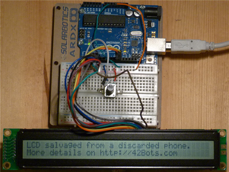
It is difficult to take a clear photo of my messy wires, so follow the <a title="Arduino LiquidCrystal library Tutorial" href="http://arduino.cc/en/Tutorial/LiquidCrystal" target="_blank">Arduino LiquidCrystal Library Tutorial</a>, for a visual of the wiring between the LCD and the Arduino.
Next: Get my “new” LCD working with a shift register (to save some Arduino pins) and mounting it on my current robot project. More on that in part two….
**References:**
* <a title="Arduino LiquidCrystal Library" href="http://arduino.cc/en/Reference/LiquidCrystal" target="_blank">Arduino LiquidCrystal Library</a>
* <a title="Arduino LiquidCrystal library Tutorial" href="http://arduino.cc/en/Tutorial/LiquidCrystal" target="_blank">Arduino LiquidCrystal Library Tutorial</a>
* <a title="HD44780 LCD Compatible Driver Document" href="https://www.sparkfun.com/datasheets/LCD/HD44780.pdf" target="_blank">Hitachi HD44780 driver</a>
* <a title="HD44780 LCD Starter Guide" href="http://www.stanford.edu/class/ee281/handouts/lcd_tutorial.pdf" target="_blank">HD44780 LCD Starter Guide</a>
Comments
Comment by Wagner on 2013-11-26 15:42:18 -0700
Nice tutorial!
Comment by Erik Burman on 2014-07-20 09:41:21 -0700
I had a similar surplus 40×2 module lying around with the same chip set that you show in your example photo. Following your tutorial I was able to wire it up correctly and get it running. Thanks!
Also I found that the lcd.clear() function does not work properly unless followed by a 1 millisecond delay:
lcd.clear();
delay(1);
Apparently the larger displays need a little time to catch up before moving on to the next instruction.
Comment by Stan on 2014-07-21 07:14:01 -0700
Thanks for the tip on the clear function!
Comment by S.Wood on 2015-05-10 17:32:37 -0700
Hello
I have 2 of the 40×2 lcd modules described in your tutorial.
I have a 16×2 lcd running ok a breadboard and Arduino.
I ran a 2’nd set of wires to the 40×2 from the breadboard and rechecked wiring
to confirm correct pin names to pin names (The names are the same on both modules)
Changed Lcd.begin to (40, 2) ,compiled and downloaded to Arduino.
The 16×2 still works, but the 40×2 does not (I tried the other 40×2 also)
Any ideas ?
I have used the 40×2 with an 8052 Basic with a 6 line initialization routine that repeated 8 bit mode 3 times before new commands were sent. This was to clear any cobwebs in case the 40×2 didn’t wake up right. I’m wondering if the lcd library has this in it.
It is very possible I missed a step.
Thanks , S.Wood
Comment by Stan on 2015-05-10 20:30:07 -0700
I did not need to do anything special to get mine working…Are you sure you got the pins of the 40×2 modules right?
Comment by Sam on 2021-04-05 07:10:58 -0700
Hey Stan-
I have a bunch of these 40×2 and 40×4 hd44780 text LCD displays. I loved the article you presented above. The link included however to wire the Arduino to the lcd is no longer active. Would you please be so kind as to provide me a wiring diagram? I will be using an UNO for this project. I am a public educator and will be doing this for a class I am teaching. I hope this is not a huge request to you it seems that you are the only one I can find who has done this. I will be hard wiring the nano to this lcd so and wont be using a bread board. Kind of awesome if i knew where land all the wires from point A to B. I’m dyslexic so pictures help a ton as well. Thank you so much for your time.