ESP8266 Introduction
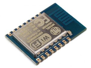
The ESP8266 is a low cost MCU with built in Wi-Fi. It can be paired with another host microcontroller, like an Arduino, to provide WiFi networking capability for a basic IoT development platform. Additionally, the ESP8266 can be used as a stand-alone MCU, as it includes a 32-bit 80Mhz processor, 16 GPIO pins (4 PWM enabled) and a built in Analog-to-Digital converter, SPI and I2C interfaces and more… The MCU has a n operating voltage of 2.5V – 3.6V and average operating current of 80 mA. Here is the official ESP8266 MCU datasheet from the Shangai-based manufacturer of the chip Espressif Systems. The most popular current version is the ESP-12E MCU pictured below. On its own this is not very friendly for prototyping, as the spacing of the pins is not compatible with standard headers and breadboards.
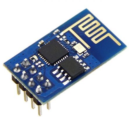
There are a number of low cost modules incorporating different versions of the ESP8266 chip on the market. Some earlier versions expose a few of the MCU I/O pins and require additional modules for programming and voltage regulation. Those were originally used to provide low cost WiFi connectivity to a master MCU, such as an Arduino compatible board. Below is break-out board of one of the older variants of the ESP8266 : ESP-01.
An open source, full development board around ESP8266 has been designed by the NodeMCU team that includes additional USB to Serial UART adapter, a micro USB port for programming and a 3.3v regulator. The NodeMCU board comes ready out-of-the-box for you to connect to your computer, install USB drivers, and start writing programs that connect to your Wi-Fi network! All of that at an average price of about $4 USD on eBay.
NodeMCU development board variants
The original and now outdated version 0.9 of the NodeMCU was apparently quite wide and covered the full 10 pins on standard breadboard. This would have made prototyping quite awkward. I do not have this version, it is now deprecated and should be avoided! You can generally can tell it apart by the yellow color that must have been cool when it was originally launched, but now should scream “stay away” to you if you see it on sale on eBay:
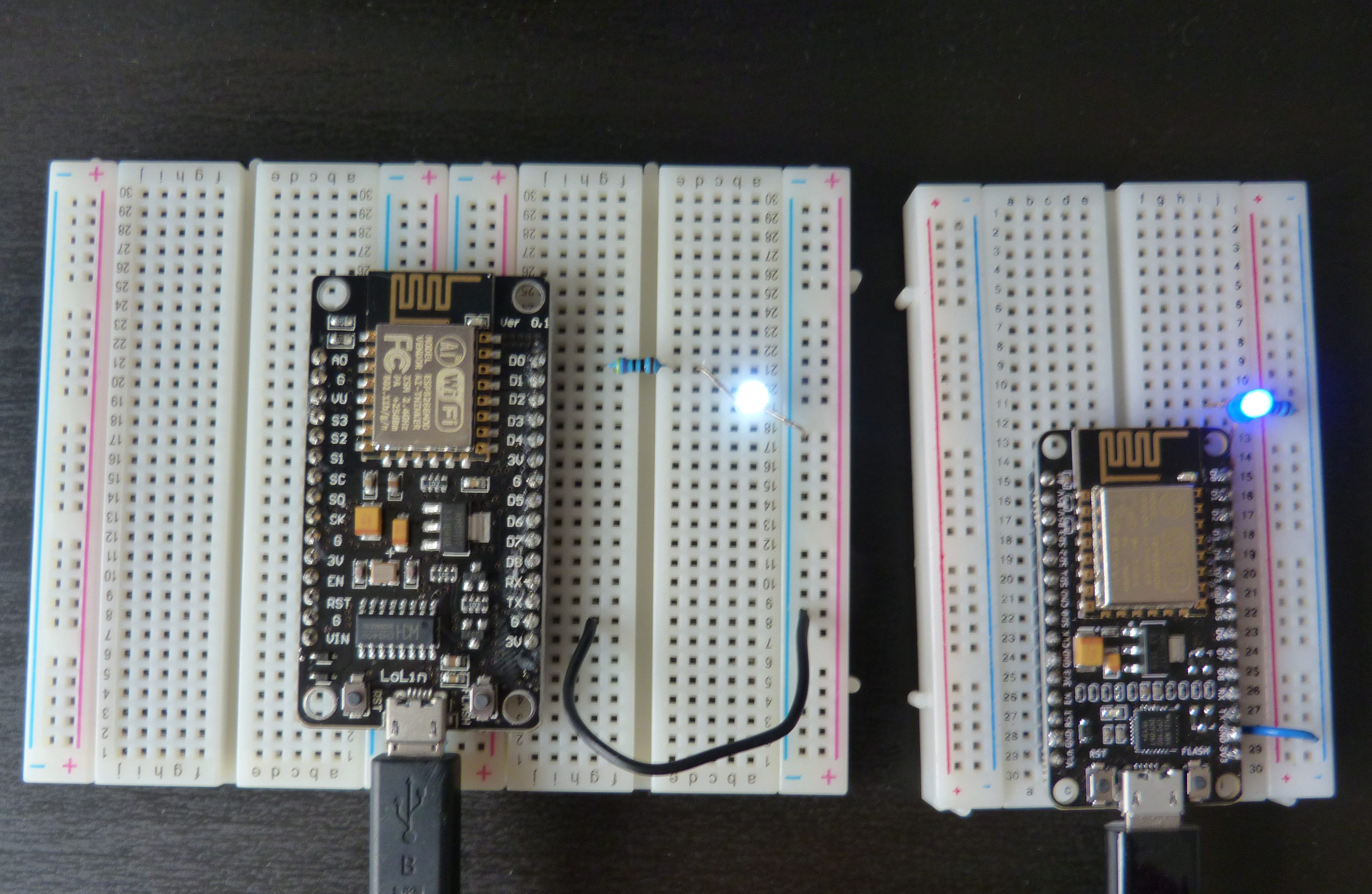
The next generation of the NodeMCU board fixes this design issue. This version fits on a single board, leaving one pin on each side on a standard breadboard to attach your other goodies. Here is an image of the board and the pin-out, courtesy of the NodeMCU team:
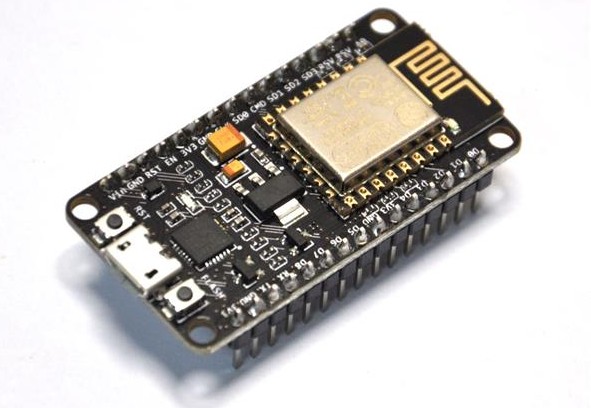
It is important to note that the pin labels printed on the NodeMCU board do not correspond to the ESP8266 MCU pins. For example, the pin marked as D0 on the NodeMCU board is actually pin GPIO16 on the ESP8266 chip. Additionally, the second generation of the NodeMCU board has a onboard LED on pin D0 (GPIO16). The onboard LED is connected in sink mode, which means that it will be ON when the D0 is set to “low” / ground and OFF when it set to “high” / 3.3v. This took me a while to figure out initially…Lastly, as a reminder the board has an on-board voltage regulator and can be powered from a standard ESB 5V connection, or through the VIN pin (5-9V). The pin-out diagram of the second generation NodeMCU board is below. The pin numbers in the blue area are the ones marked on the board, with the corresponding ESP8266 GPIO pin and function on the outside.
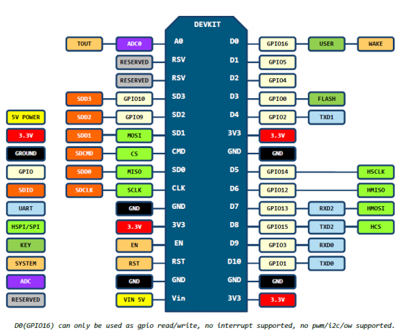
This second generation of the NodeMCU development kit is labeled by the NodeMCU team as V1, but most Chinese retailers refer to it as V2.
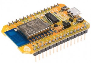
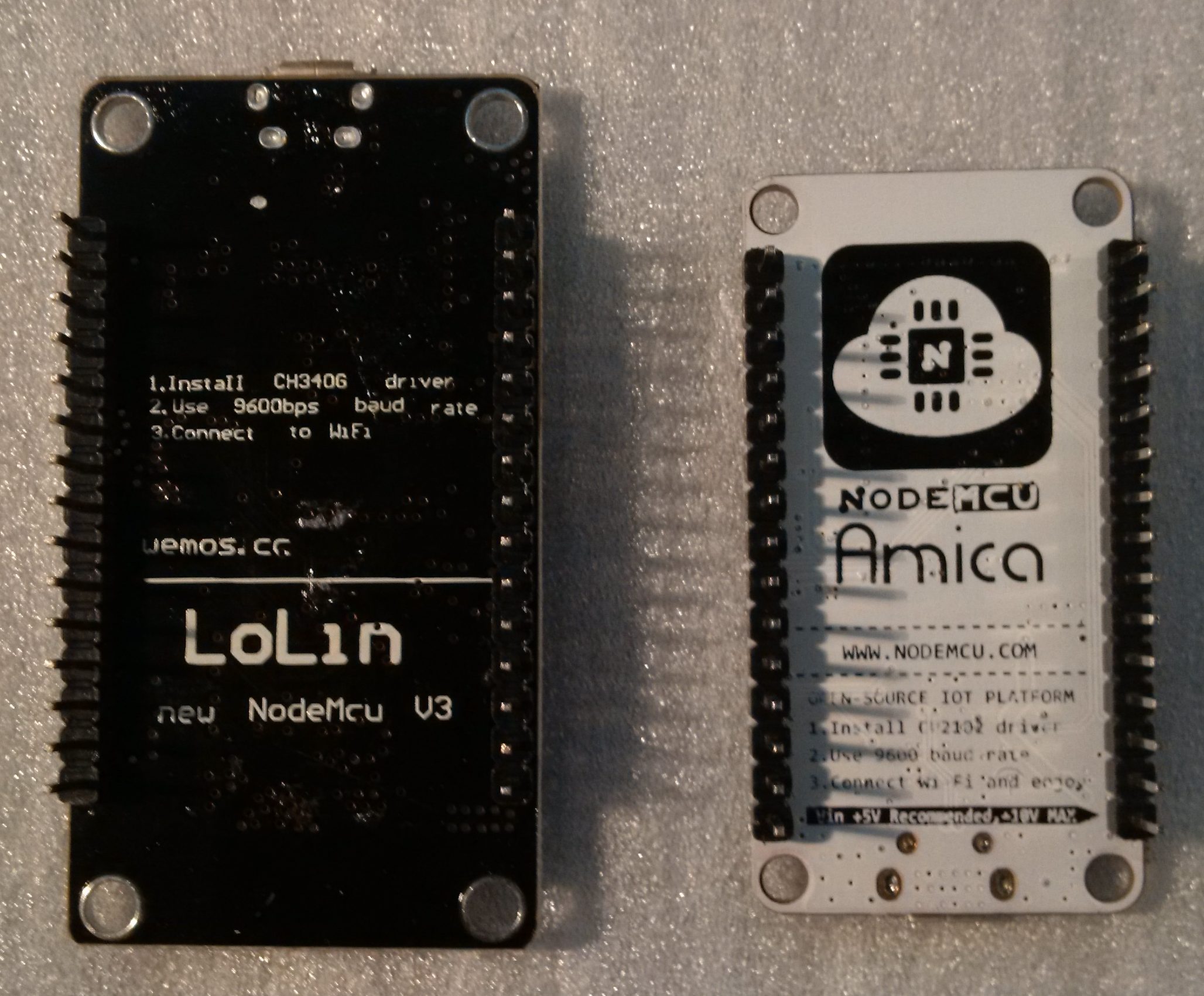
What may be even more confusing is that there is a NodeMCU V3 sold in many places. The “V3” is not based on an official design released by the NodeMCU team. Although this “V3” version uses the same ESP-12E version of the ESP8266, there are a couple of differences, some more obvious than others. Firs, the “V3” is bigger and does not fit a standard breadboard. It can straddle two breadboards, though side by side to allow for more space to connect additional components.
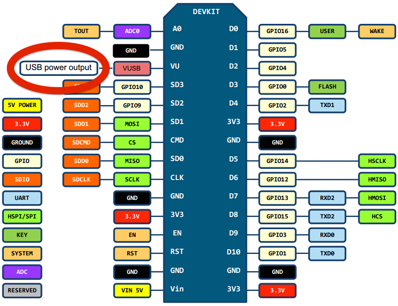
Additionally, the V3 board does not have an onboard LED on pin D0 (GPIO16) and two of the reserved pins in the slimmer versions are re-purposed as USB Vin and Ground pins. Here is a pinout of the larger “V3” variant courtesy of the WEMOS Electronics site:
Last, but not least the two NodeMCU development board variants use different USB to serial chips, which means you need to have different drivers installed on your development box: CP2012 on the original, slimmer version and CH340G on the wider “V3” board. Some people have reported problems with the CH340G on Mac. I have both drivers installed on my Windows 10 box and have no issues with either. I will be using the the NodeMCU second generation (slimmer) development kit in most future tutorials. Given the already low price of the NodeMCU dev kits, the only reason I can think of to use any of the other ESP8266 breakout boards for a hobby project would be the lower form factor of the minimalist ESP8266 boards.
ESP8266 Programming Tools
AT+Command Processor
By default, most versions of the boards come with the “AT” firmware, which basically lets you use these devices as simple wireless modems controlled through a serial port. This was the primary method of using the ESP8266 chips initially by the community, in most cases to provide cheap Wi-Fi connectivity to another microcontroller, like an Arduino board. Here is a list of the ESP8266 AT command set and their description.
Espressif SDK
Expressif has released freely an ESP8266 SDK and development toolset. There are a few options for building the toolchain on Linux and OSX, plus some options in Windows. Here is a detailed ESP8266 SDK getting started guide from Espressif. I have not attempted to use this toochain directly and it definitely looks that some effort will be required to get things properly installed and configured initially. The upside is that you will have access to more features and options, than what is available via the AT commands.
NodeMCU Development toolkit
The same team that creates the NodeMCU board also came up with a development toolkit. Thw cire is an eLua based firmware for the ESP8266 WiFi SOC from Espressif. The firmware is based on the Espressif NON-OS SDK 2.0.0. Through the NodeMCU toolkit commands are sent to the ESP8266 via the Serial UART interface, interactively. The NodeMCU firmware also allows us to save our applications as a script in the ESP8266‘s flash memory, and instruct it to run the application code every time it restarts. More details an examples can be found on the NodeMCU GitHub project page.
Arduino IDE (my preferred option)
This community project brings support for ESP8266 chip to the Arduino environment. It lets you write sketches using familiar Arduino functions and libraries, and upload them as firmware on the ESP8266 module and run them directly and on power-up. ESP8266 Arduino core comes with a number of useful libraries for WiFi communication, useing a file system in flash memory, work with SD cards, servos, SPI and I2C peripherals. The ESP8266 module support is added to the Arduino IDE (version 1.6.4 and later) using the “Boards Manager”. Given that I am familiar with the Arduino IDE, libraries and code syntax this is my preferred method of programming my NodeMCU board, covered in this tutorials.
Here is my detailed tutorial on how to add the ESP8266 core to the Arduino IDE.