After testing the basic Wi-Fi connectivity options of the ESP8266 it is now time to explore some of the more interesting features of the chip. In the sketch below the NodeMCU development board creates a Wi-Fi access point and starts a web-server. A HTML page hosted on the web-server displays analog data from a photocell and allows you to control remotely a LED via Wi-Fi from a web-browser on your phone or PC. As in the previous examples, I am using the Arduino IDE to program the ESP8266 board.
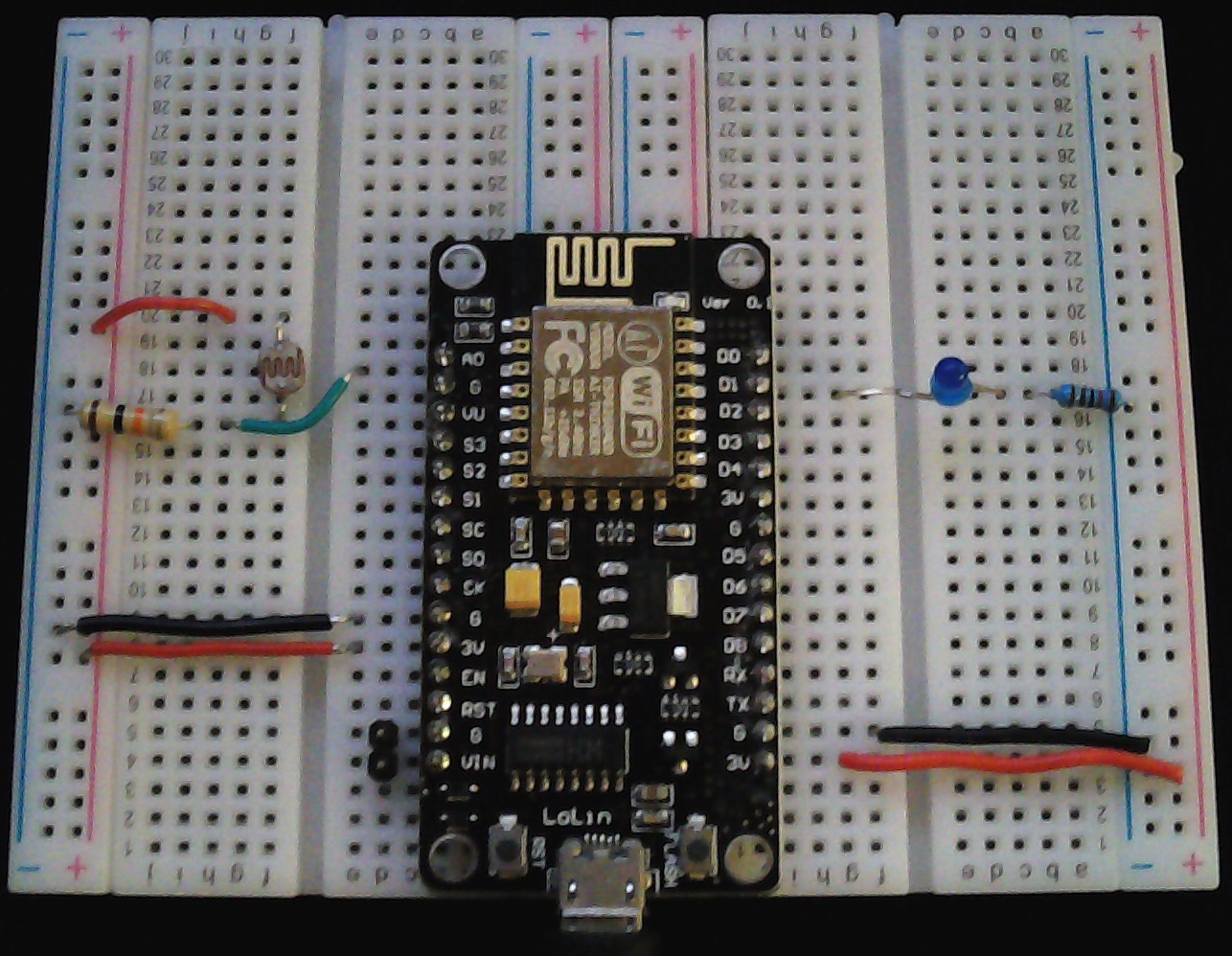
The LED is connected to NodeMCU pin D1 (ESP8266 GPIO5) through a 1k resistor. One leg of the photocell is connected to 3.3v and the other one to ground trough a fixed 10k Ohm (or higher) resistor. There is also a connection from the NodeMCU pin A0 (ESP8266 ADC0) to the point between the fixed pull-down resistor and the variable photocell resistor.
And here is the sketch:
Load the sketch, open the serial monitor and restart your NodeMCU module. You should see the following output:
Configuring access point...
AP IP address: 42.42.42.42
HTTP server started
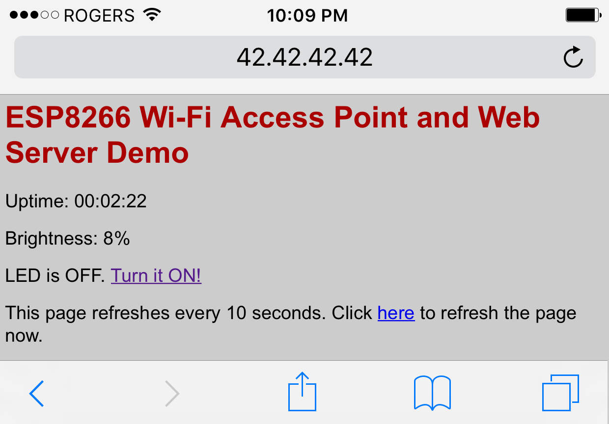
Now open the Wi-Fi settings of your phone, or PC. You should see a new Wi-Fi network, called “ESP8266” (assuming you left the defaults in the sketch above). Connect to it using the password from the sketch, open a new browser window and type http://42.42.42.42 in the address bar. This is the static IP we defined earlier in the sketch for the root of the web-server. You should see a page like the one below:
You can click on the link to toggle the LED now: the page should refresh and the LED should respond to your command!