I while back I did some work on a self-balancing robot using and Arduino Uno and the InvenSense MPU-6050 6DOF sensor. Using the sensor is easy, thanks to Jeff Rowberg’s I2Cdev library and sample code. If you look around line 200 of the MPU6050_DMP6 example arduino sketch that comes with the library you will see the following:
// supply your own gyro offsets here, scaled for min sensitivity
mpu.setXGyroOffset(220);
mpu.setYGyroOffset(76);
mpu.setZGyroOffset(-85);
mpu.setZAccelOffset(1788); // 1688 factory default for my test chip
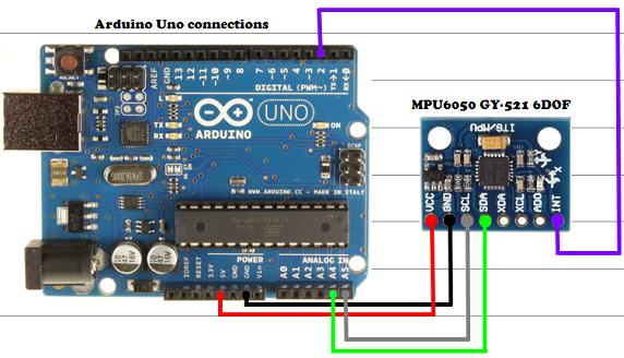
I did some further reading on the I2CDev forum and found several threads on calibrating the MPU-6050 sensor and determining the optimal offsets. These, apparently, are specific to your device, as well to the exact orientation of the module, once it is installed. I found a significant improvement using the script by Luis Rodenas attached to this forum thread. Below is the Arduino sketch version 1.1 (the most current at the time of this post). For best results, mount your module and run the script, while you have it stable in the position you will use it. For example, on a self balancing robot, have the robot upright in the optimal balanced position and keep it steady while the script completes and you see output with the suggested offsets. You then need to copy these offsets and overwrite the defaults in the sample code (around line 200, as mentioned above).
// Arduino sketch that returns calibration offsets for MPU6050 //   Version 1.1  (31th January 2014)
// Done by Luis Ródenas <[email protected]>
// Based on the I2Cdev library and previous work by Jeff Rowberg <[email protected]>
// Updates (of the library) should (hopefully) always be available at https://github.com/jrowberg/i2cdevlib

// These offsets were meant to calibrate MPU6050's internal DMP, but can be also useful for reading sensors.
// The effect of temperature has not been taken into account so I can't promise that it will work if you
// calibrate indoors and then use it outdoors. Best is to calibrate and use at the same room temperature.

/* ==========  LICENSE  ==================================
 I2Cdev device library code is placed under the MIT license
 Copyright (c) 2011 Jeff Rowberg

 Permission is hereby granted, free of charge, to any person obtaining a copy
 of this software and associated documentation files (the "Software"), to deal
 in the Software without restriction, including without limitation the rights
 to use, copy, modify, merge, publish, distribute, sublicense, and/or sell
 copies of the Software, and to permit persons to whom the Software is
 furnished to do so, subject to the following conditions:

 The above copyright notice and this permission notice shall be included in
 all copies or substantial portions of the Software.

 THE SOFTWARE IS PROVIDED "AS IS", WITHOUT WARRANTY OF ANY KIND, EXPRESS OR
 IMPLIED, INCLUDING BUT NOT LIMITED TO THE WARRANTIES OF MERCHANTABILITY,
 FITNESS FOR A PARTICULAR PURPOSE AND NONINFRINGEMENT. IN NO EVENT SHALL THE
 AUTHORS OR COPYRIGHT HOLDERS BE LIABLE FOR ANY CLAIM, DAMAGES OR OTHER
 LIABILITY, WHETHER IN AN ACTION OF CONTRACT, TORT OR OTHERWISE, ARISING FROM,
 OUT OF OR IN CONNECTION WITH THE SOFTWARE OR THE USE OR OTHER DEALINGS IN
 THE SOFTWARE.
 =========================================================
 */

// I2Cdev and MPU6050 must be installed as libraries
#include "I2Cdev.h"
#include "MPU6050.h"
#include "Wire.h"

///////////////////////////////////   CONFIGURATION   /////////////////////////////
//Change this 3 variables if you want to fine tune the skecth to your needs.
int buffersize=1000;     //Amount of readings used to average, make it higher to get more precision but sketch will be slower  (default:1000)
int acel_deadzone=8;     //Acelerometer error allowed, make it lower to get more precision, but sketch may not converge  (default:8)
int giro_deadzone=1;     //Giro error allowed, make it lower to get more precision, but sketch may not converge  (default:1)

// default I2C address is 0x68
// specific I2C addresses may be passed as a parameter here
// AD0 low = 0x68 (default for InvenSense evaluation board)
// AD0 high = 0x69
//MPU6050 accelgyro;
MPU6050 accelgyro(0x68); // 100 && i<=(buffersize+100)){ //First 100 measures are discarded
      buff_ax=buff_ax+ax;
      buff_ay=buff_ay+ay;
      buff_az=buff_az+az;
      buff_gx=buff_gx+gx;
      buff_gy=buff_gy+gy;
      buff_gz=buff_gz+gz;
    }
    if (i==(buffersize+100)){
      mean_ax=buff_ax/buffersize;
      mean_ay=buff_ay/buffersize;
      mean_az=buff_az/buffersize;
      mean_gx=buff_gx/buffersize;
      mean_gy=buff_gy/buffersize;
      mean_gz=buff_gz/buffersize;
    }
    i++;
    delay(2); //Needed so we don't get repeated measures
  }
}

void calibration(){
  ax_offset=-mean_ax/8;
  ay_offset=-mean_ay/8;
  az_offset=(16384-mean_az)/8;

  gx_offset=-mean_gx/4;
  gy_offset=-mean_gy/4;
  gz_offset=-mean_gz/4;
  while (1){
    int ready=0;
    accelgyro.setXAccelOffset(ax_offset);
    accelgyro.setYAccelOffset(ay_offset);
    accelgyro.setZAccelOffset(az_offset);

    accelgyro.setXGyroOffset(gx_offset);
    accelgyro.setYGyroOffset(gy_offset);
    accelgyro.setZGyroOffset(gz_offset);

    meansensors();
    Serial.println("...");

    if (abs(mean_ax)<=acel_deadzone) ready++;
    else ax_offset=ax_offset-mean_ax/acel_deadzone;

    if (abs(mean_ay)<=acel_deadzone) ready++;
    else ay_offset=ay_offset-mean_ay/acel_deadzone;

    if (abs(16384-mean_az)<=acel_deadzone) ready++;
    else az_offset=az_offset+(16384-mean_az)/acel_deadzone;

    if (abs(mean_gx)<=giro_deadzone) ready++;
    else gx_offset=gx_offset-mean_gx/(giro_deadzone+1);

    if (abs(mean_gy)<=giro_deadzone) ready++;
    else gy_offset=gy_offset-mean_gy/(giro_deadzone+1);

    if (abs(mean_gz)<=giro_deadzone) ready++;
    else gz_offset=gz_offset-mean_gz/(giro_deadzone+1);

    if (ready==6) break;
  }
}
Comments
Comment by Utsav Vakil on 2016-05-07 08:25:30 -0700
Hey I used your code and it is working perfectly. I want to know the theory behind the calibration code. Is there any place I can know this theory?
Comment by webmarka on 2016-06-23 00:12:44 -0700
I discovered that the cause of the problem for me was having the 6050 mounted upside down relative to gravity during the chip callibration. I had soldered the header block on the top, but using it in the bread board required orienting the chip upside down.
Comment by SPSS on 2016-07-03 23:18:50 -0700
That concludes the basic calibration of the MPU-6050; the sensor should now be more than accurate enough for most applications, such as self-balancing robots and quad-copters.
Comment by Eqbal Khan on 2016-07-16 08:54:27 -0700
I have done some work and made a auto calibration of mpu6050’s accelerometer and gyroscope. I have discussed some problems and It needs improvement. See my post at:http://www.i2cdevlib.com/forums/topic/91-how-to-decide-gyro-and-accelerometer-offsett/
Comment by John Gardner on 2017-01-17 22:56:41 -0700
basically from what I can see, the serial readout is the raw data from the chip. If you set this chip on a true flat surface, with all axis facing exactly 90 degrees to one another, and you get a reading of say x-10 y20 z -5, then you write the offset as x +10 y -20 and z+5, then you will get a reading of zero from all axis. That’s what calibration is all about, making sure your numbers are what they should be in a known environment. I hope this helped you to understand the theory of calibration.
Now for a word: I am not long into arduino and all this. about 2 months. I’ve worked with machine tools a lot, I’ve built computers a lot, and I’ve tinkered here and there into electronic kits and experiment boards as a kid. I could be totally off base above, but I think I’ve got it right.
Comment by Tanguy on 2017-02-03 14:54:00 -0700
Hey, ok I know it isn’t the subject but i couldn’t find the answer anywhere else…
My Gyro is set on a +/- 200°/sec scale range but I would like to put it to +/- 2000°/sec scale range…
Could someone help me and tell me how to do so ?
Thank you verry much !!
Comment by Aditya Sood on 2017-04-14 04:24:41 -0700
Arduino: 1.8.2 (Windows 10), Board: “Arduino/Genuino Mega or Mega 2560, ATmega2560 (Mega 2560)”
AutoCallibration_PID:51: error: ‘buff_ax’ does not name a type
buff_ax=buff_ax+ax;
^
AutoCallibration_PID:52: error: ‘buff_ay’ does not name a type
buff_ay=buff_ay+ay;
^
AutoCallibration_PID:53: error: ‘buff_az’ does not name a type
buff_az=buff_az+az;
^
AutoCallibration_PID:54: error: ‘buff_gx’ does not name a type
buff_gx=buff_gx+gx;
^
AutoCallibration_PID:55: error: ‘buff_gy’ does not name a type
buff_gy=buff_gy+gy;
^
AutoCallibration_PID:56: error: ‘buff_gz’ does not name a type
buff_gz=buff_gz+gz;
^
AutoCallibration_PID:57: error: expected declaration before ‘}’ token
}
^
exit status 1
‘buff_ax’ does not name a type
This report would have more information with
“Show verbose output during compilation”
option enabled in File -> Preferences.
Comment by HaleyB on 2017-07-29 13:05:56 -0700
Hi, I’m having this same error (‘buff_ax’ does not name a type”).
Was this ever resolved?
Comment by Frank on 2017-08-31 07:15:07 -0700
The code above is incomplete. For full code see
http://forum.arduino.cc/index.php?action=dlattach;topic=397918.0;attach=206004
Comment by JimD on 2018-03-02 05:51:29 -0700
Thanks for the complete code.
Comment by vivek on 2018-05-18 00:10:34 -0700
Hi
i am trying to use it with 9250, i have changed the reference from 6050 to 9250 but I get an error message
” no matching function for call to ‘MPU9250::MPU9250(int)’ ”
I am a beginner and trying to learn, I have an MPU9250 and would like to cal liberate it, so please explain. I am using MPU9250_master libraries.
Comment by Stephanie Kim on 2019-01-17 04:31:44 -0700
Hi! The link to the calibration code is no longer valid; is it possible for you to email me or post the zip file/code please?
Comment by satya on 2019-09-24 06:13:33 -0700
I am trying to interface the mpu 650 module to node mcu to calibrating the values for robot i am
trying to useed the display the calibrating values (X-Y axis) please provide the code for node mcu.
thankyou.
Comment by satya on 2019-10-24 05:38:32 -0700
I have a problem with MPU6050 gyro sensors, I am making school project with Vehicle Accident GPS tracking. When the normal condition, eventhing is ok. Gyro is working his axis,but when over limit gyro’s x,y,z values, LCD and Serial monitor is stop their process. how can i do that?
Comment by Rasha Ghaddar on 2020-10-12 13:07:47 -0700
Hi, I’m working on building a quadcopter that level it self at a certain height,
does this code work?
Or anyone code provide me with a code ?
Thank you
Comment by Simon on 2023-02-23 00:29:34 -0700
I’ve just done a LOT of work and detailed analysis of MPU6050 calibration
– there is a writeup here: https://github.com/btsimonh/mpu6050-pigpio-client/wiki/MPU6050-Calibration-registers—including-Fine-Scale
The discovery of the way fine scale operates helps a lot in understanding the device….