A while back I bought the InvenSense MPU-6050 sensor in a “GY-521” breakout board from eBay. For a long time it sat quietly in my box of “possibly cool things to check in the future”. Recently, I decided to finally get to building a self-balancing robot and dug it out. As with almost anything from eBay, it came with no documentation.
The MPU-6050 breakout boards are quite popular in the Arduino community and information was easy to find. Even too easy: it took me a while to sift through many partial, or “almost” working implementations before I found a relatively easy to use, clean and reliable set of instructions and Arduino sample code. So here it is documented for future reference!
MPU-6050 Overview
According to the InvenSense MPU-6050 datasheet, this chip contains a 3-axis gyroscope and a 3-axis accelerometer. This makes it a “6 degrees of freedom inertial measurement unit” or 6DOF IMU, for short. Other features include a built in 16-bit analog to digital conversion on each channel and a proprietary Digital Motion Processor™ (DMP) unit.
The DMP combines the raw sensor data and performs some complex calculations onboard to minimize the errors in each sensor. Accelerometers and gyros have different inherent limitations, when used on their own. By combining the data from the two types of sensors and using some math wizardry (a process referred to as sensor fusion), you apparently can get a much more accurate and robust estimate of the heading. The DMP on the MPU6050 does exactly that and returns the result in “quaternions”. These can then can be converted to yaw-pitch-roll, or to Euler angles for us humans to read and understand. The DMP also has a built in auto-calibration function that definitely comes in handy, as we will see later.
The biggest advantage of the DMP is that it eliminates the need to perform complex and resource intensive calculations on the Arduino side. The main downside is that it seems that the manufacturer did not provide much information on the proprietary inner workings of the DMP. Nevertheless, smart and creative folks figured out how to use its main features, and were nice enough to share the results with the rest of us. You can still pull the raw, accelerometer and gyro data as well, disabling the DMP, if this works better for your application, or you want to apply your own filtering and sensor fusion algorithms.
The MPU-6050 communicates with a microcontroller through an I2C interface. It even has a built in an additional I2C controller, that allows it to act as a master on a second I2C bus. The intention is for the IMU to read data from say, an external magnetometer (hooked up via those XDA / XCL pins you see on the breakout board) and send it to the DMP for processing. I have not found much detail on how to make the DMP use external magnetometer data yet, but fortunately that is not needed for my self-balancing robot at this point.
Lastly, the MPU-6050 has a FIFO buffer, together with a built-in interrupt signal. It can be instructed to place the sensor data in the buffer and the interrupt pin will tell the Arduino, when data is ready to be read.
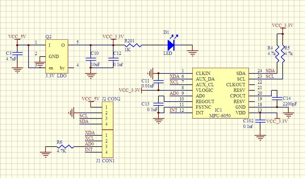
MPU-6050 / GY-521 break-out board schematics
Below is the schematic of the GY-521 break-out board for the MPU6050 chip.
Hooking the MPU-6050 / GY-521 to an Arduino Uno
The InvenSense MPU6050 chip is a 3.3V IC, with a working voltage range of 2.375V-3.46V, according to its datasheet. As you can see from the schematics above, the GY-521 breakout board has a built in low drop-out voltage regulator, so it is safe to power the chip through the Arduino 5V rail. This is recommended, as due to the voltage drop-out of the regulator on the VCC line, using the Arduino 3.3V rail may not provide enough voltage. I tested powering the chip both with 3.3V and 5V from the Arduino successfully, but in my final set-up opted for the 5V input.
Based on what I have read online and what I saw on my tests, the 3.3V SDA / SCL lines of the IMU work fine connected directly to the corresponding Arduino 5V I2C pins. If you want to be absolutely safe, you could use a level shifter, voltage divider, or an inline 10k resistor to protect the MPU6050 I2C lines. I opted for simplicity over safety, in my set-up and (so far) all is well.
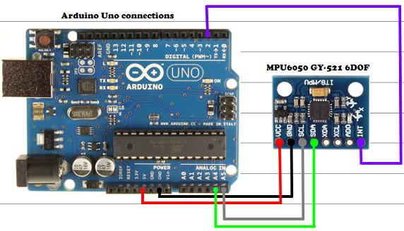
| MPU6050 / GY-521 |
| VCC |
| GND |
| SDA |
| SCL |
| INT |
Arduino libraries and example code
Here is where credit and a big thanks is due to Jeff Rowberg for his I2Cdev library and sample code for interfacing with the InvenSense MPU6050 chip and partially reverse-engineering the DMP functions. Also, you might check out the “teapot demo” post from Debra at “Geek Mom Projects” that pointed me to the i2cdev library in the first place.
To get started you need to follow these simple steps:
- Download the I2C Device Library ( i2cdevlib ) master zip file and extract the contents to a convenient location on your hard-drive.
- You should see a folder called “i2cdevlib-master” that will contain an “Arduino” subfolder in it and a couple of other items, that we do not need.
- Open the Arduino folder and locate the “I2Cdev” and “MPU6050” sub-folders. Those are the two Arduino libraries we will need to copy to your Arduino libraries folder (here is how to install an Arduino library, in case you have not done this before).
Under the Sketch->Examples menu, you should now see a menu item for the newly installed MPU6050 library. Load the MPU6050_DMP6 example and follow the instructions in the sketch comments to define what type of serial output you would like to see from the sensor. I suggest using yaw-pitch-roll or Euler while you are testing things out, as the data is a bit more intuitive.
Find the section in the code (around line 100) in the MPU6050_DMP6 example sketch and uncomment the #define OUTPUT_READABLE_YAWPITCHROLL line. Then make sure that all other output options are commented out. Here is the section for the yaw/pitch/roll output for reference:
// uncomment "OUTPUT_READABLE_YAWPITCHROLL" if you want to see the yaw/<br />
 // pitch/roll angles (in degrees) calculated from the quaternions coming<br />
 // from the FIFO. Note this also requires gravity vector calculations.<br />
 // Also note that yaw/pitch/roll angles suffer from gimbal lock (for<br />
 // more info, see: http://en.wikipedia.org/wiki/Gimbal_lock)<br />
 #define OUTPUT_READABLE_YAWPITCHROLL<br />
If all is well, when you upload the sketch to the Arduino and open your serial monitor (remember to set it at the correct baud rate), you will be prompted to send a random character via serial.
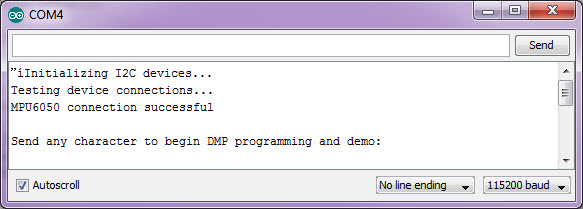
Once you type any character in the serial input field and hit “Send”, a few status messages will appear and (if all is well) a steady stream of data from the IMU will follow!

I charted the DMP output of the sensor (the yaw-pitch-roll data), while the breakout board was set still on a “relatively” flat service. As you can see, initially some sort of calibration algorithm is run by the DMP. Once that completes, the sensor values are very stable.
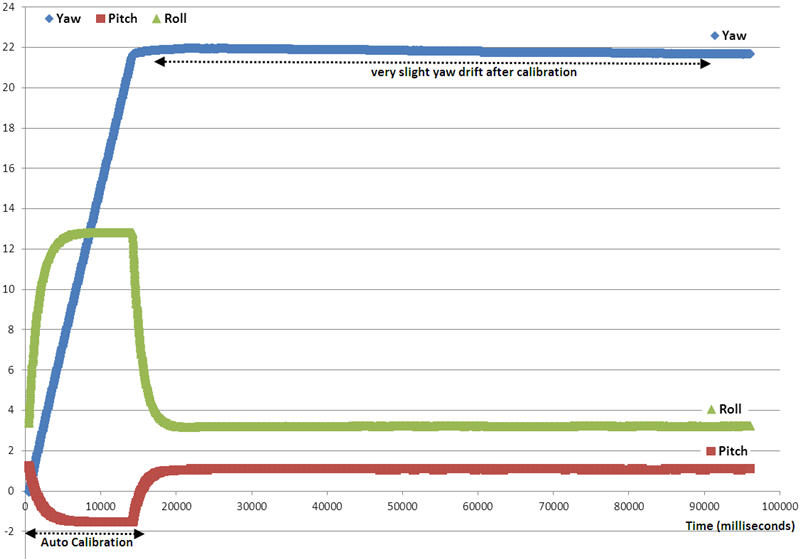
With 6 axis IMUs you can expect yaw drift. After the initial auto-calibration, the DMP compensates for most of that and only a very slight yaw drift remains (the light blue line).
Even better results can be achieved with some additional fine-tuning of the offsets in the sample code of the MPU-6050. Arduino MPU-6050 auto-calibration sketch courtesy of Luis Rodenas.
For my self-balancing robot, I will initially use the roll axis only which is very steady. Next: use the MPU-6050 to get my self-balancing robot to…well, balance!
Comments
Comment by Farhan on 2014-04-09 01:39:23 -0700
Hi,
Thanks for quite useful information.
I tried the similar code but the values I am getting for yaw,pitch and roll are as follows;
ypr -68.69, 55.04, 0.55
ypr -68.63, 55.08, 0.54
something similar. Why I am getting too much high values for yaw and pitch while the sensor is in static position.
Could you please help me in this regards.
Thanks.
Farhan
Comment by Stan on 2014-04-09 10:12:20 -0700
Hi Farah, I would imagine this is a result of the initial position of your sensor. The data I posted is when my sensor is flat on its back (the IC and the passive components on the board are facing up). There might be some calibration issues as well, but I am definitely not an expert there. I suggest checking / posting on the I2CDevLib forum:
Stan
Comment by Jenish on 2014-04-12 07:05:49 -0700
Please help me in finding the error. I get the error message ‘DMP Initialization failed (code 1)’.
What should i do? Reply me, please!!
Comment by Stan on 2014-04-12 10:35:47 -0700
Hi Jenish, do you have the interrupt pin connected? What Arduino board variant are you using? If your set-up is different than mine, you may want to try the I2CDeVlib forum, it is very active: http://www.i2cdevlib.com/forums/
Comment by Rada on 2014-05-10 02:46:39 -0700
I tried to collect data from mpu6050 but I didn’t get it until I found this site! Thanks a lot!
Comment by Stan on 2014-05-10 13:52:10 -0700
You are welcome, thanks for taking the time to post back!
Stan
Comment by jihen on 2014-05-14 03:14:17 -0700
i followed the whole instructions, but once i open my serial monitor, i didn’t receive anything just a white background, what that means? there is an error?
Comment by Stan on 2014-05-14 09:16:27 -0700
Hi jihen, I would suggest to doubleckeck your connections and make sure that you have selected the correct baud rate in the serial monitor (it should match the one you set in your sketch).
Stan
Comment by Daniel on 2014-05-25 09:02:52 -0700
hi, great tutorial, i’m too using the mpu6050 for make a self-balancing robot but i’m having a lot o problems can you help me? can i take a look in yours self-balancing robot?
Comment by Stan on 2014-05-25 14:29:58 -0700
Hi Daniel, to be honest I have not done much on this project since the intial prototype here:
http://42bots.com/showcase/an-arduino-self-balancing-robot-working-prototype/
You can find a copy of the code here: https://codebender.cc/sketch:32392
Warning: The code is a rough first prototype and needs a lot of work. For example: the call to the pid function should be around line 286, near the comment “// other program behavior stuff here”. Also most of this code is from the MPU6050 example and is not really needed for the purpose at hand.
I would suggest to get things working one by one on your own (motor control, the IMU, the PID function…) . Here is a great resource on PID: http://brettbeauregard.com/blog/2011/04/improving-the-beginners-pid-introduction/ that helped me a lot.
Good luck, and post back if you make progress!
Comment by Simone on 2014-05-28 13:12:10 -0700
Hi
that’s a really good post. I’ve read a lot of those in this days and this one is the only
which make a reference about the 10-20 seconds that the MPU 6050 needs in order
to stabilize the data (in your example YPR but it is the same also for the other outputs “type”).
However I still not understand why this period (that you call “Auto Calibration”) is so long. The
datasheet of the MPU 6050 says it should be about 30ms.
Moreover, in this days, I have discovered that a lot of “MPU-6050 & I2Cdev users” doesn’t have this “Auto Calibration” time of 20s when they start their sketches.
Do you know what might causes this problem? I can’t figure it out yet 😐
Thanks for your attention, and good luck with your blog!
PS: I’m going to read the segwey one ASAP 😀
Comment by deck on 2014-06-05 14:13:20 -0700
I did test the code and it worked fine, I found one problem thou. It seems, that the Gyro doesn’t go back to the original values, after you pitch or roll it for a few seconds. If you have it lying on a flat table, move it around and then put it back, it should output the same angles as before the movement. But in my case it is off by a degree or so. The effect gets worse when you move it longer or in more extreme angles. What could be the reason?
Can this be solved with sensor fusion? Any idea?
thank you and kind regards,
deck
Comment by Stan on 2014-06-05 16:48:18 -0700
Hi deck, I have only used the DMP values of the sensor so far. Sorry, not sure what can be the cause for that. I would suggest to post a question in the i2cdevlib forum: http://www.i2cdevlib.com/forums/ .
Stan
Comment by Somesh on 2014-06-16 10:10:25 -0700
Hi Stan,
I got my circuit up properly and with the i2c-scanner sketch the slave is detected at 0x68. I got I2CDev and MPU6050 in libraries/ folder. I am trying to get the MPU6050_DMP6 sketch to compile on Arduino IDE (1.0.1 ubuntu) now, but file I2CDev/msp430_i2c.c has a header which the compiler is not able to find.
Are there any other installations/libraries I need to do use beside the Arduino Core libraries and i2cdevlib ??
thanks,
Somesh
Comment by Somesh on 2014-06-16 10:11:56 -0700
The missing header file is msp430.h
Comment by Kumar on 2014-06-25 11:18:02 -0700
Hi,
First thanks for nice article. Recently I interfaced ADXL335 and it has X,Y,Z pinouts to AVR MCU WORKING FINE.Today i purchaced MPU6050 accelerometer but there is not X,Y,Z pins in it can you please help me on it.
Comment by Stan on 2014-06-26 10:52:19 -0700
Everything you need to get readings from the MPU6050 is covered in the post and in the i2cdevlib sample code by Jeff Rowberg.
Comment by caymanguy on 2014-06-28 00:30:27 -0700
https://www.youtube.com/watch?v=kIss1mZJWPs
Comment by SimonR on 2014-06-28 13:38:41 -0700
Stan – thanks for posting this! I’ve been trying to get this damn board to work all day, but with the addition of your DMP code, suddenly, it produces good values!
Give yourself a gold star!
Comment by Snehal Patel on 2014-07-31 11:39:06 -0700
cool!!!! You save me lots of my time….
Good job with ease of code…
thanks a lot
Comment by Firoz Dang on 2014-08-02 15:52:04 -0700
Great thanks man…. I tried this today and it works great….I was not able to do it with so many other codes…thanks again….
Comment by Emsity on 2014-08-27 14:10:03 -0700
Many thanks for this great article.
I brought a MPU6050 from ebay (arrived by China post). I hooked it up as instructed, but all I can see is goobledeegook letters.
Any ideas?
Comment by Stan on 2014-08-27 21:04:48 -0700
I would doubleheader that the baud rate in the serial monitor matches that of the sample sketch.
Comment by Guilhem on 2014-09-01 07:13:24 -0700
Hey Stan and the others,
Thanks a lot for the sketch and the advices, it compiles well and works quite fine. However I still have a couple of problems:
– as you say in your post, even after calibration, I always get values that are not equal to 0 whereas I’m on a flat table
ypr 33.63 0.28 0.55
ypr 33.63 0.28 0.55
Is there a way of changing the DMP code or the MPU6050’s library to set the values to 0 when calibrated ? Otherwise this can easily be corrected in the arduino sketch by retrieving the calibrated values at each measurement, so this is not my main concern
-My may concern is that the angles seem not right at all for the pitch and roll (around 30° for a real 45 degrees angle, around 70° for a 90° angle, and never gets to 90 even by turning the sensor by more than 90 degrees…). Has someone the same problem ? Is it coming from the code ? Or maybe my sensor is fucked…!
Thanks a lot for your answers!
Guilhem
P.S.: I guess this is more an electronic problem, but when adding a servo moto which angle depends on the MPU6050 values, after a few seconds is starts turning right and left likre crazy and the accelerometer values start fluctuating a lot, any idea ? (I added a capacitor to limit current fluctuations, but maybe it’s not enough,…)
Comment by Tyrone on 2014-09-02 21:20:39 -0700
Hello Stan,
I could use your help with the PID you used with the balance robot. After carefully studying the ” int pid() “part.
I am confused on how the PID ” out”, controlls the motors to keep the bot balanced.
(int out = (int)pid * (-1); // not worried about correct rounding here
return out;) Out is only stated here in the code once.
I understand in the code how ” drive(0,0);” can move the balance bot motors while its balancing.
But how and where in the code is the PID “out” equal to
void drive(int leftMotorSpeed, int rightMotorSpeed). To keep the balance bot balanced.
Now to tell you what I am trying to accomplish with your PID.
I have spent a great deal of time learning about encoders. So I can be sure that both motors on the balance robot move at the same speed, and return to the correct position if pushed.
So how do I connect just the ” leftMotorSpeed” to the “out” of the pid, so only that motor is part of the PID?
There are other PID codes out there I could use, but yours is the one i want to use. Just a little confused.
Thank you for your help.
Tyrone
Comment by Martin on 2014-09-11 00:42:38 -0700
Hi Stan,
Really great article. Many thanks. I’m starting out – with almost no experience at all.
I see you’ve connected the SDA/SCL pinouts from the MPU to Pins A4/A5 on the Arduino.
I have the latest version of the Arduino, with SDA/SCL pins (I2C bus) on the Digital Data port.
I would have assumed that the logical” way to connect the GY-521 board to the Arduino would be to linkup both of the SDA/SCL pairs, on each side.
My question is: why did you not use the SDA/SCL pins on the Arduino?
Comment by Stan on 2014-09-11 16:22:54 -0700
Hi Martin, glad to see you found the write-up helpful! As far as I know, the SDA and SCL pins that are near to the AREF pin on the Arduino Uno are essentially connected to the A4/A5 pins. The Atmega328p on an Uno uses the A4/A5 pins for I2C. The pins were duplicated near the AREF pin to allow for compatibility of shields across certain Arduino boards. Bottom line, you can use either pin combo, but if you communicate via I2C, you can’t use the A4 / A5 pins on the Uno for anything else. See the notes here: http://arduino.cc/en/Main/ArduinoBoardUno and here: http://forum.arduino.cc/index.php/topic,141609.0.html.
Cheers, Stan
Comment by Morduino on 2014-09-20 04:07:46 -0700
Thank you for your effort. I have trouble with serial monitor outputs. Also, when the baud rate is as listed above 115200, the serial monitor screen goes blank. Trying with a different baud rate, it initializes but no further data appears and the readings are zero.
Comment by Xavier on 2014-09-24 20:42:10 -0700
Hey there! Thanks for the tutorial! 🙂
I just want to ask you one silly question! Those Roll angles that you get from the DMP correspond to the rotation around the X axis indicated on the chip? Or do they correspond to the Y axis on chip?
Comment by Shrest on 2014-09-30 06:46:03 -0700
Im have a similar problem, I get zero offset of around 0.5, about 14deg for 15 deg angle, about 28 deg for 30. I was looking for solutions to make it more accurate. Could you a solution for improving your readings, if yes, please share.Thanks.
Comment by Hohite Fetene on 2014-10-13 10:38:49 -0700
I wanted a code to compile a raw data thats detects an angle for a segway. I havea 6 axis gyro sensor with an arduino. can you please help me out.
Comment by riz on 2014-10-20 08:28:12 -0700
stan your blog is very helpful indeed. i’ve chosen inverted pendulum as my final year project. i have this confusion though. euler angles that we get by using DMP example sketch, does it need any more filtering like complementary filter or kalman filter. or these values can be used as it is further without sensor fusion and things? looking forward to your answer!
Comment by Stan on 2014-10-21 08:35:43 -0700
Thanks, Riz, I am glad you found the post helpful. From what I read about this sensor, you have two possible paths: (1) get the raw output of the accelerometer and gyro and do your own filtering and merging of the sensor data (2) get the output of the proprietary, built in DMP module, which does that for you. The advantage of option (1) is that you have more control and can merge the data with readings from other sensors, like a compass. I have only tried the second approach, but Jeff Rowberg’s library definitely allows you to pull the raw readings from the sensors as well.
Comment by Kashifa on 2014-10-22 00:18:20 -0700
Hi Stan
I followed all the steps listed but when I compiled the sketch it gave me the problems:
Exception in thread “Thread-309” java.lang.NoClassDefFoundError: Could not initialize class gnu.io.RXTXPort
at gnu.io.RXTXCommDriver.getCommPort(RXTXCommDriver.java:808)
at gnu.io.CommPortIdentifier.open(CommPortIdentifier.java:343)
at processing.app.Serial.(Serial.java:160)
at processing.app.Serial.(Serial.java:77)
at processing.app.debug.Uploader.flushSerialBuffer(Uploader.java:77)
at processing.app.debug.AvrdudeUploader.uploadViaBootloader(AvrdudeUploader.java:175)
at processing.app.debug.AvrdudeUploader.uploadUsingPreferences(AvrdudeUploader.java:67)
at processing.app.Sketch.upload(Sketch.java:1671)
at processing.app.Sketch.exportApplet(Sketch.java:1627)
at processing.app.Sketch.exportApplet(Sketch.java:1599)
at processing.app.Editor$DefaultExportHandler.run(Editor.java:2380)
at java.lang.Thread.run(Thread.java:619)
Im searching for the solution online but cant find anything helpful to remove them.’
Please help!
Regards
Comment by Kashifa on 2014-10-22 01:43:33 -0700
Hi
I managed to solve the problems listed above but after compiling it says MPU6050 connection failed and DMP initialization failed (code 1).
I tested all my connections and they are fine, can’t seem to find the reason why the MPU6050 failed.
Comment by Kashifa on 2014-10-23 04:31:48 -0700
Hi
I followed all the steps and when I ran the code it said MPU connection failed and DMP initialization failed(code 1)
Please help!
Comment by Nicolás on 2014-12-12 08:04:42 -0700
Hi! I have the same problem, could you finally resolve it? I’m using an arduino UNO R3.
Comment by Jacob Williams on 2015-01-04 10:54:13 -0700
whats the solution for ‘MPU6050’ does not name a type ???? 🙁
Comment by bharath on 2015-01-19 10:22:55 -0700
If i am moving my palm having imu sensor vertically,Then can i have the height of the hand raised from initial position…If u can calculate it how presice is it..plz do reply
Comment by RATHISH KUMAR.K.P on 2015-01-20 10:31:01 -0700
Hi
I managed to solve the problems listed above but after compiling it says MPU6050 connection failed and DMP initialization failed (code 1).
I tested all my connections and they are fine, can’t seem to find the reason why the MPU6050 failed.
Reply ↓
Comment by Clonkex on 2015-01-28 23:29:21 -0700
Does the MPU-6050 REQUIRE the interrupt to be connected to the Arduino? Because without the pin connected, the I2C bus can’t see the device. From what I can tell (by reading a couple of registers on the MPU-6050), the motion interrupt is turned on, so why on earth is the pin required??
Comment by Clonkex on 2015-02-10 18:07:55 -0700
Ah, don’t worry, I finally figured it out. I wasn’t using a common ground between the power supply of the MPU-6050 and that of the Arduino. Now it works just fine without the interrupt pin connected 🙂
Comment by Heather on 2015-03-03 02:10:17 -0700
Just wondering was is the interrupt time/at what speed are samples being taken?
Comment by Heather on 2015-03-04 06:00:02 -0700
What is the interrupt time/ how often are samples being taken for this code? cheers
Comment by James on 2015-03-17 16:18:01 -0700
I’m trying to use an Arduino Pro Mini (ATmega328 5V 16MHz), I keep getting the error during compile:
/Documents/Arduino/libraries/MPU6050/MPU6050.h:611:17: error: candidate is: uint8_t MPU6050::getMotionStatus()
uint8_t getMotionStatus();
Any help is appreciated.
Thank You
Comment by Stan on 2015-03-22 15:51:27 -0700
James, I do not have a 5V Arduino Pro Mini at the moment, so can’t replicate the problem. You will probably have much better luck posting your problem here: http://www.i2cdevlib.com/forums/forum/2-mpu-6050-6-axis-accelerometergyroscope-invensense/
Comment by James on 2015-03-25 18:19:49 -0700
Perfect. Found the answer in less than 10 min (https://github.com/jrowberg/i2cdevlib/issues/146 if you’re curious)
Comment by hasan on 2015-03-28 06:04:16 -0700
was very good
Comment by Linden on 2015-05-13 05:37:57 -0700
This is a great little tutorial and had me up and running about 5 minutes after reading it! There are so many half baked tutorials out there for this board, I wish I had found this first as it would have saved me a lot of wasted reading and searching time!
Thanks very much Stan!!!
Comment by AmieraSyafika on 2015-05-16 01:25:35 -0700
Hai Stan;
i’m now doing a project for balancing a rov. i use mpu 6050 as my imu sensor. i have some problem on how to connect my motor with the sensor. i use l293d. i take the reading value from #define OUTPUT_READABLE_YAWPITCHROLL
my question is, how i can modified the coding? let say if my yaw value is >30 i need to on the motor until it reach 30. can you help me? thank you
Comment by AmieraSyafika on 2015-05-16 07:09:29 -0700
Hai;
i’m now doing a project for balancing a rov. i use mpu 6050 as my imu sensor. i have some problem on how to connect my motor with the sensor. i use l293d. i take the reading value from #define OUTPUT_READABLE_YAWPITCHROLL
my question is, how i can modified the coding? let say if my yaw value is >30 i need to on the motor until it reach 30. can you help me? thank you
Comment by Jonathan on 2015-05-19 20:23:46 -0700
Great turorial, just worked on the first try.
Comment by xpeace on 2015-06-09 13:21:54 -0700
I also got severe problems with 90° angles using the default DMP6 YPR example.
Tilting the sensor to +/-90° results in +/-80° degrees output,
very slowly increasing to +/-90° in about 10-15 seconds (Pitch + Roll).
Yaw values seemed more reasonable, …
Arduino Nano + MPU6050 DMP6 Code Example.
Any help on this issue is highly appreciated.
Comment by Friedemann on 2015-06-10 03:03:57 -0700
I have a very similar Problem, instead of 90° I get only like 80° – the Values is very slowly increasing (15-20 seconds).
Arduino Nano V3 DMP6 standard Example.
Comment by Sarvesh Thakur on 2015-06-24 23:30:27 -0700
I have included all these header files and still my code is not compiling. It is stuck.
—code removed—
can anyone help?
Comment by Stan on 2015-06-25 14:13:57 -0700
Hi Sarvesh, if you followed the wiring instructions above, installed both the i2cdev and MPU6050 libraries, then this should work (I tested it over the week-end as I re-started my work on a self-balancing robot). Usually, compiling errors occur if a library is missing. If you are still having problems, you may have more luck posting your question on the http://www.i2cdevlib.com/forums/. The specific error message you are getting when you run the vanilla examples from the MPU6050 libraries will help.
Comment by Sam on 2015-09-21 22:17:14 -0700
The yaw is probably drifting because it can’t be corrected with the gravity vector from the accelerometers. Even a perfect gyro will drift in heading from the earth’s rotation. Thus 9 DOF sensors with magnetic feelers. But I wonder if it isn’t already doing a true north calculation by finding the axis with the least angular change relative to gravity. Thanks to earth’s rotation it’s possible to fix yaw drift everywhere except at the poles… as exploited by the gyrocompass.
Comment by Mayur on 2015-09-25 12:01:17 -0700
Hi Stan,
First of all I really appreciate all the efforts you put in making such a great article. So thanks for that. Second of all, I’m posting here just to realize what tool did you use to draw the circuit diagram ? As I can guess, you didn’t use Proteus, because It doesn’t have MPU-6050 library in it and Eagle is also out of question. It’s just that I need to draw this circuit for my project but with minor modifications.
So if you could please help me out.
To other readers, I’m all ears.
Thanks again. Have a good day ahead.
–
Mayur
Comment by Stan on 2015-09-26 18:57:54 -0700
Hi Mayur, I believe I started with Fritzing, but then edited the image directly in an image editing program.
Comment by Steven on 2015-11-12 17:52:53 -0700
Thank you, I was stuck at the initialize failed code 1 but manage to get through it using your library!
This is my demo: https://youtu.be/tWWCofzJDck
Comment by Stan on 2015-11-13 08:52:31 -0700
Steven, glad you made it work and thanks for posting back! This is not my library, though. All credit should go to Jeff Rowberg. Cheers, Stan
Comment by JIN on 2016-01-08 05:37:10 -0700
can you help me how to make 2 mpu6050 working simultineously?
Comment by afzal on 2016-02-05 05:41:08 -0700
how i can interface two or more mpu6050 and how i can i made connection and pin interrupt ?
Comment by Stan on 2016-02-06 17:21:02 -0700
Never tired that, sorry…
Comment by muhammad ezzat on 2016-02-12 07:00:01 -0700
hi dude! nice project there! i’m ezzat, now i’m trying to make a project similar with this https://www.youtube.com/watch?app=desktop&persist_app=1&v=WTkMdCqo9hg
but i didnt know how to make so the mpu6050 will send the data to processing screen..please help me..thanks alot..
u can reach me at [email protected]
thanks again.
Comment by Abhishek on 2016-02-15 09:30:03 -0700
Hi Stan,
I’m working on “AIR MOUSE”(final year project).
I have a MPU6050 gyro/accelerometer/temperature sensor for mouse control. And “how can I make use of accelerometer values from your code to position mouse cursor on computer”. I want real co-ordinates of mouse on PC from the tilt of the MPU6050 IMU sensor. How to do that? I am using Arduino UNO R3. Sorry for my bad English. Please help me out in this.
Thanks
Comment by Rhythm khanna on 2016-02-19 07:04:46 -0700
Hello author,
First of all thank you so much for a useful and complete guide on how to use the sensor with arduino to build cool projects. My project is smewhat different as I want to build a gesture recognition algorithm that can determine arm length gestures using this mpu6050. The pitch, roll and yaw values are great for determining static orientation but I am confused about detecting complete movement of the hand. It will be of great help if you or anyone can guide me on this. I will mention you on my capstone project report as contributors. 🙂
Thank you.
Comment by Maddo on 2016-03-12 10:48:14 -0700
Hello
First thanks to the author for this good guide and the Sketch.
I tried it out with a LED. It schuld light up when I move the MPU. That worked prettx fine.
Now I tried to Control a servo, but it always tells me “FIFO oveflow”.
What coauld be a reason for this?
Here you can see how I want to control the servo:
if(euler1 * 180/M_PI >5 || euler1 * 180/M_PI 5 || euler[2] * 180/M_PI <-10)
{
for (pos = 0; pos = 0; pos -= 5) {
servo1.write(0);
delay(15);
}
}
I hope somebody can help me to solve the Problem.
Thanks in advance.
Comment by Maddo on 2016-03-12 10:49:48 -0700
And here is the missing “else-part”
else
{
for (pos = 180; pos >= 0; pos -= 5) {
servo1.write(0);
delay(15);
}
Comment by Stan on 2016-03-16 08:12:49 -0700
Hi Maddo, I would guess it is the delay(15) function you used. You could rewrite this using the method in the “Blink Without Delay” example.
Comment by Jiangyan on 2016-07-26 18:45:18 -0700
I have the same problem. the pitch value can not reach 90°.
when i put the sensor vertical , Pitch value can only 70°+.
when i put the sensor 60, Pitch value can only 45°+.
when i put the sensor 30, Pitch value can only 20°+.
etc…
Comment by Mimansa on 2016-09-22 06:05:43 -0700
I am getting very drastic fluctuations when in editing the same DMP_6 example code as per my requirement.I just added few simple lines for blinking of led along with my the examples line present.
Comment by whiletrue on 2016-12-09 08:07:47 -0700
Nice post, thanks for that. Can you please share how to stop/sleep the MPU6050? I want to be able to activate/desactivate it remotely but I’m not finding how to deactivate it anywhere. Thanks in advance.
Comment by Sarwade Narasing J. on 2016-12-19 05:59:13 -0700
Hi stan,
Please look at schmatic of MPU6050 given in following datasheet on page no 22
https://www.invensense.com/wp-content/uploads/2015/02/MPU-6000-Datasheet1.pdf
explain me where should i connect pin 8 (VLOGIC) of MPU6050 ic.
i connected it to gnd via capacitor.
Comment by bala on 2017-01-01 20:44:44 -0700
Hi im getting this error when i try to add the library to my Arduino. can anyone help please.
Specified folder/zip file does not contain a valid library .
Comment by sid on 2017-02-11 05:58:00 -0700
Hi Stan,
i tried for the example code from MPU6050 example MPU6050_DMP6 it gave no error in compiling.when i uploaded it serial monitor was showing MPU6050 connection failed but i2c scanner detected i2c device at port 0x68 what should i do
Comment by JaJoMa on 2017-02-17 02:38:40 -0700
thank you for your article.
we use it for an scoll projekt but after the message “Initializing I2C devices…”.
I don’t know what to do know. Hope you can help.
Comment by avadhoot kesarkar on 2017-03-21 13:27:59 -0700
Thanks stan for info on MPU 6050….:)
Comment by Len Manning on 2017-06-21 14:21:38 -0700
I have set this up as per instructions, and it communicates and talks to the serial monitor.
However I appear to get a set of random numbers generated.
Do you think the board is broken?
It is lying on the desk with the IC upwards not moving.
Printout below.
euler 18.49 nan 44.46
euler -180.00 -1.95 -173.34
euler 10.85 3.89 -3.89
euler -179.60 -0.06 179.99
euler 30.31 nan 61.53
euler -29.27 42.85 156.64
euler 180.00 0.00 -180.00
euler -55.09 nan 106.28
FIFO overflow!