I have recently started exploring an ESP8266 based development board I had sitting around. There is a growing number of firmware and development tools for the board, but as I am familiar with the Arduino IDE and syntax, I decided to give it a shot first. If you are familiar with Lua, you might be more comfortable checking out the NodeMCU project. Those guys created an open source hardware development board around the ESP8266 MCU with included USB interface for easy programming and power and custom firmware and development tool-chain to program the ESP8266 module using Lua.
In this and following tutorials I will be using the NodeMCU variant ESP8266 development board, but will stick to the familiar Arduino IDE for the software part. The Arduino IDE does not support the ESP8266 MCU out of the box, but luckily some smart folks have created a custom ESP8266 board definition that is easily added to the IDE. The steps are very similar to those that I used before to add support for the ATtiny85 chips to the Arduino IDE. You can find source code, details on the project and other resources on their GitHub repository: Arduino core for ESP8266 WiFi chip.
Step 1: Install the Arduino IDE
Likely, you have this covered, but you obviously will need the Arduino IDE installed. As the support for the ESP8266 is added via the “Additional Boards Manager” feature, you will need a current version of the IDE (version 1.6.4 or above).
Open the Arduino IDE and go to: File->Preferences
Copy the ESP8266 core definition link below into the “Additional Boards Manager URLs” field:
http://arduino.esp8266.com/stable/package_esp8266com_index.json
If you (like me) already have board definitions added to the filed, separate the values with a comma, or expand the field and paste the link on a new row.
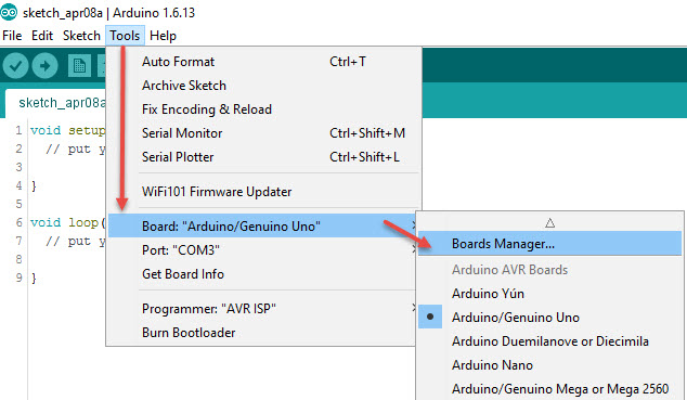
Click OK to save your changes and close the Preferences screen. Next, navigate to the Boards Manager: Tools->Board: “<Some Board>” ->Boards Manager…
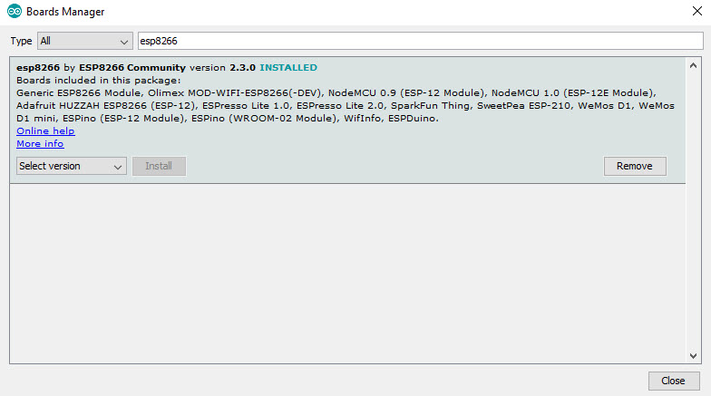
Once on the Boards Manager screen, type ESP8266 in the search box and you should see an entry called “esp8266 by ESP8266 Community”. Hit the install button and prepare for great things to happen!
The installation process may take a few minutes, as a lot of files will be downloaded and installed, but at the end you should see a screen like this:
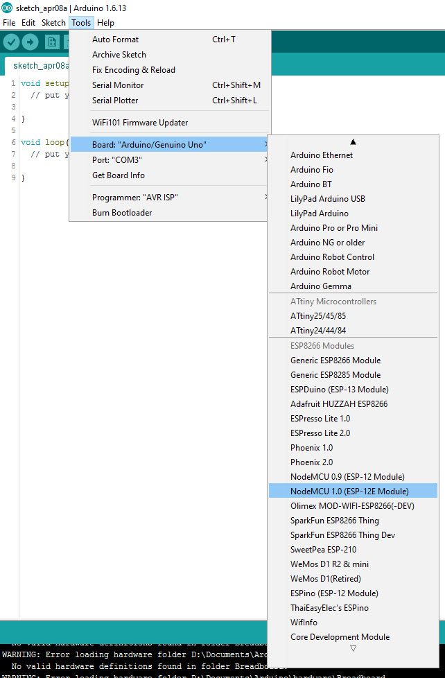
To verify all is well, close the Board Manager screen and go back to the Tools->Board: “<Some Board>” menu. You should see a bunch of new boards listed as options:
Congratulations, you now have your Arduino IDE configured to program ESP8266 based development boards.
I use the second generation (v1.0) of the NodeMCU development board with the ESP-12E version of the ESP8266 MCU (the highlighted option above) and will recommend to buy that one, so you don’t have to fiddle with separate USB / UART to serial converters and awkward pin-outs that are not breadboard friendly. It is a no-hassle Internet of Things development board that goes for less than US $4 on eBay and Aliexpress and for a bit more from your local online retailer, if you are in North America.
For more details on the NodeMCU board variants and pin-out diagrams, see my previous post. Next – loading a blink sketch on our ESP8266 development kit using the Arduino IDE.
One last thing to note, depending on the version of the NodeMCU board you have and the state of your development box, you may need to install USB drivers for either the CH340G or the CP2012 USB to serial chip. If you have programmed Arduino clones already, chances are you have both drivers installed. Here is a link to the official driver for the CP2012. The official CH340G driver is available from the manufacturer’s site. A fair warning: the CH340G official driver page is in Chinese, so it requires a leap of faith if you are not familiar with the language.