How to program the ESP8266 WiFi Modules with the Arduino IDE (Part 2 of 2)
Part 1 of this tutorial covers the set-up of the Arduino IDE to support the ESP8266 boards. In part 2 I will go through the steps of loading a slightly modified Blink sketch to the NodeMCU board. First, a couple of things to be aware of when working with the ESP8266 boards:
Power: ESP8266 is a 3.3v board
The NodeMCU version of the board has an on-board 3.3v voltage regulator and can be powered from the USB port (5V), or through the vin pin (5-7.5v recommended). All GPIO pins work at 3.3v and the board may be damaged, when connected directly to 5v Arduino compatible modules. Additionally, the maximum current that can be sourced from a digital pin is 12 mA. Use a high value resistor for LEDs (1k Ohm) and do not connect servos, motors, or other peripherals that draw large current.
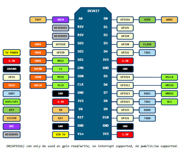
Pin mappings: NodeMCU
As mentioned in the previous post, if you are using one of the more popular NodeMCU board variants you can refer to the pin mappings below. In the Arduino sketch, you can refer to the ESP8266 pin by their GPIO number (for example, if you have a LED on GPIO16: int ledPin = 16;), or by the pin printed to on the NodeMCU board (example: int ledPin = D0;).
ESP8266 Firmware and the Arduino IDE Board Manager
Once you load your Arduino sketch on the ESP8266 you are essentially overwriting the default AT firmware on the ESP8266. There are two parts to the program that you are loading: your compiled sketch and the ESP8266 binary firmware to support the low-level API calls to the ESP8266. You can easily restore the original firmware on the ESP8266 MCU using one of the firmware flashing tools available.
The Arduino ESP8266 board definition library available via the Arduino Boards Manager manager is based on the Espressif NonOs SDK. Version 2.3.0 (the latest available through the Arduino IDE Boards Manager) is based on nonOS SDK 1.5. There is an nightly build version of the board definition based on the latest version 2.0 of the NonOS SDK. The most often asked for features in v2.0 of the nonOS SDK are related to security: support of TLS 1.2 (required by some cloud based services, like Watson IoT) and WPA2. Non of these are needed for our basic sketch below, though and I am using the ESP8266 Board library version 2.3.0 below.
Modified Blink Sketch for the ESP8266
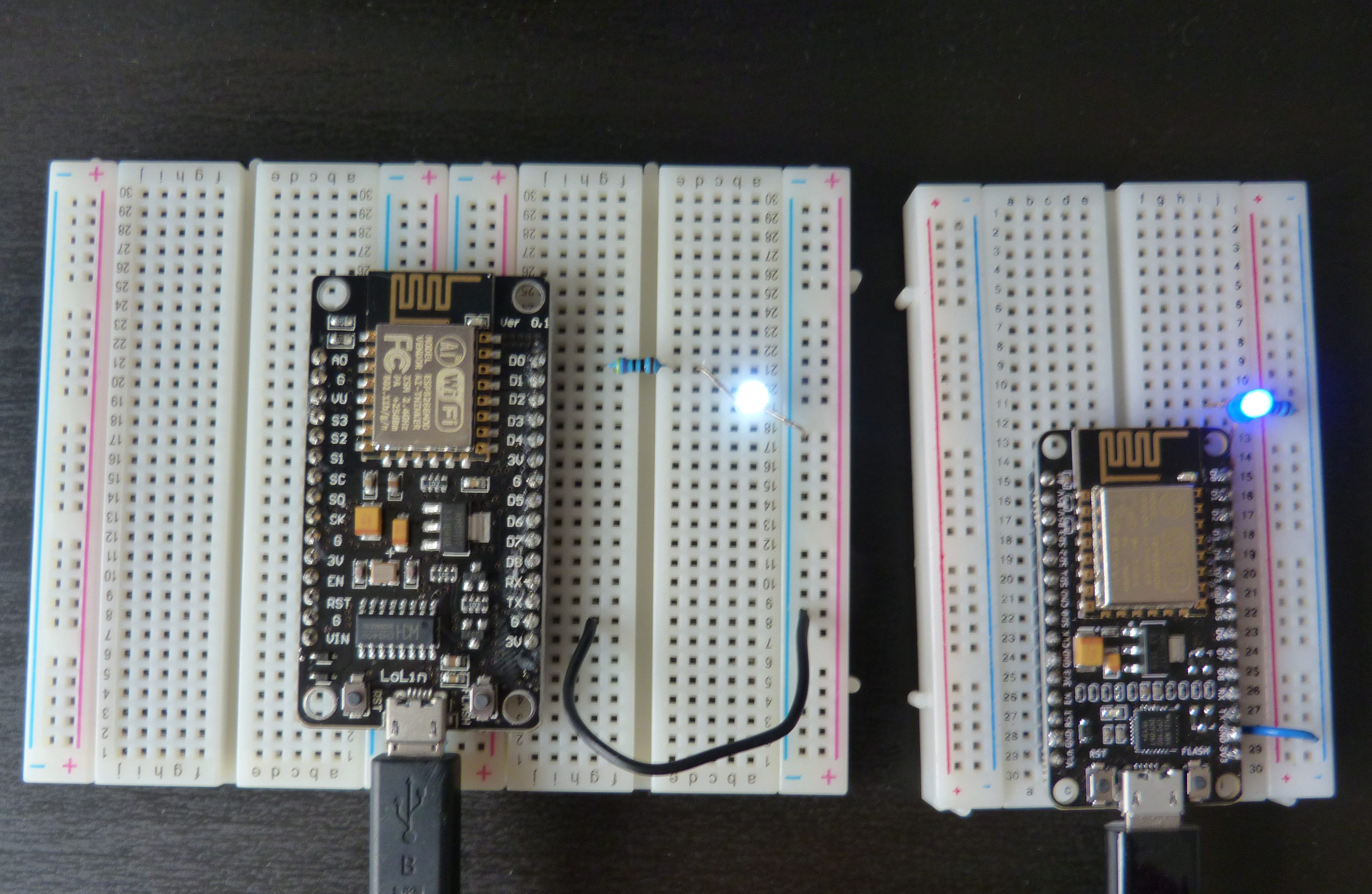
Finally, let’s get that LED blinking! Connect a LED between pin marked as D0 on NodeMCU board and ground through a current limiting resistor (1000 Ohm or higher). If you are using a skinnier NodeMCU board that fits on a single breadboard, there will also be a onboard LED connected to the same pin. Note that the onboard LED is wired in sink mode, e.g. it will light up when the pin is set to LOW and will turn off when it is set to HIGH. Here is the actual sketch I used:
/*
** ESP8266 Blink Sketch - more on http://42bots.com
** Note that you need to use the D0, D1...format to address the pins printed
** on the nodeMCU board. For the pin mapping diagram see:
** https://github.com/nodemcu/nodemcu-devkit-v1.0
** Connect an LED between pin marked as D0 on NodeMCU board and ground through
** a 470 Ohm resistor (as a minimum). The onboard LED for NodeMCU Dev Kit Board v2
** is on GPIO pin 16, marked as D0 on the board. The wider "unofficial" v3 of the
** NodeMCU board has no onboard LED. The onboard LED is connected in sink mode:
** it will be on when the pin is set to low (ground). If you have an LED connected
** to pin D0 it will be high, when the onboard LED is low.
*/
int ledPin = D0;
// int LedPin

void setup() {
  pinMode(ledPin, OUTPUT);   // Initialize the ledPin pin as an output
}

// the loop function runs over and over again forever
void loop() {
  digitalWrite(ledPin, LOW); // Onboard LED is on, and the LED connected to pin D0 is off.
  delay(1000);               // Wait for a second
  digitalWrite(ledPin, HIGH);// Onboard LED is off, and the LED connected to pin D0 is on.
  delay(2000);               // Wait for two seconds
}
Connect the NodeMCU board to a USB port on your computer, make sure the correct board is selected and upload the sketch.
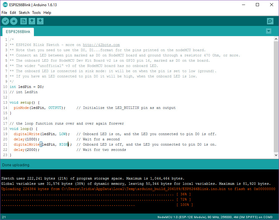
You should see the LED blink and your Arduino IDE ESP8266 programming environment is now fully set-up and tested!
You guys are great..
This information was very helpful
Arduino: 1.6.13 (Windows 8.1), Board: “NodeMCU 1.0 (ESP-12E Module), 80 MHz, Flash, Legacy (new can return nullptr), All SSL ciphers (most compatible), 4MB (FS:2MB OTA:~1019KB), 2, v2 Lower Memory, Disabled, None, Only Sketch, 115200”
Board nodemcuv2 (platform esp8266, package esp8266) is unknown
Error compiling for board NodeMCU 1.0 (ESP-12E Module).
This report would have more information with
“Show verbose output during compilation”
option enabled in File -> Preferences.