Arduino controlled LCD using a shift register and the SPI library
Now that I got my recycled 40×2 character LCD working with Arduino, the next step is to get it to show something useful. I decided to add it to my Bluetooth Controlled robot and display data from its two ultrasonic distance sensors (initially). Gradually more interesting info like battery voltage and wheel encoder data can also be shown, as I get those components working. The problem is that now I need to find another 6 digital pins to control the LCD itself. Fortunately, there is an alternative: add a 74HC595 shift register and take advantage of the Arduino SPI library. Here is how:
In this case, I want to send data one way only – from the Arduino to the LCD. Using a shift register gives me 8 additional digital output pins (in the case of the 74HC595) at the cost of 3 Arduino digital pins (for one way communication from the Arduino to the shift register via SPI).
Step 1: Wiring the Arduino, the 74HC595 shift register and the LCD
- The Arduino Uno communicates with the shift register using SPI . The Arduino is the “Master” and the shift register is the “Slave”. For this purpose we need the Data (MOSI), Clock (SLCK) and Latch (Slave Select) pins connected. The MISO (Master In Slave Out) line is not needed because we are not going to read any data from the LCD.
- The character LCD is now connected to the shift register pins, not directly to the Arduino. A byte is sent from the Arduino each clock cycle, which then tells the shift register how to set each of its 8 digital pins (high or low).
Connections between the Arduino and the shift register:
The data bits (MOSI): Connect pin 14 “DS” on the 74HC595 to Arduino pin 11.
The SPI clock (SCK): Connect pin 11 “SHCP” on the 74HC595 to Arduino pin 13.
The Latch: Connect pin 12 “STCP” on the 74HC595 to Arduino pin 9.
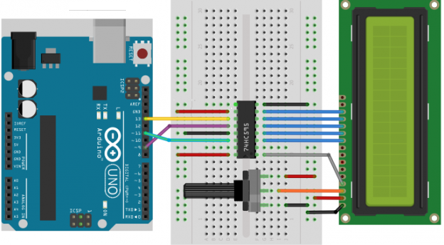
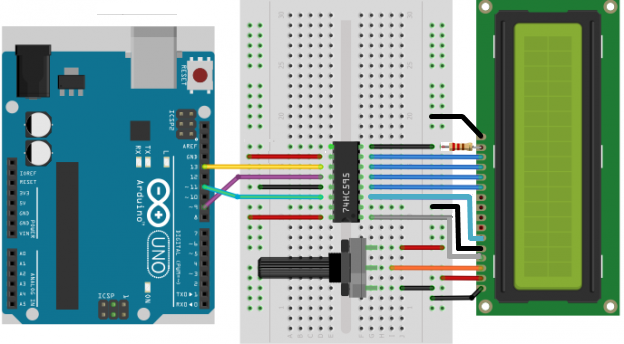
Here is a diagram of the connections (updated on June 8th, 2015):
Wiring Notes:
Some LCDs do not have a backlight (pins 15 and 16 on the LCD). In the diagram above pin 15 (tha anode of the backlight) is connected to the 5v rail through a 220 Ohm current limiting resistor. On most LCD modules, a current limiting resistor is already built in on the LCD module, so you may not need to add one. Naturally, if your LCD does not have a backlight (has 14 pins only) you do not need to worry about that at all.
The trimpot connected to pin 3 of the LCD (labeled V0 on my module) controls the brightness of the display. One thing to note is that the display may be the brightest when its pin 3 is connected to ground. If you do not have a trimpot, I would suggest to do just that.
Step 2: Adding SPI support to the Arduino LiquidCrystal library
By default the LiquidCrystal library that comes pre-installed with the Arduino IDE (I am using version 1.0.5) assumes a direct connection between the Arduino and the LCD. Fortunately, there is a modified version of the LiquidCrystal library that adds support for SPI, created by Juan Hernandez, in the Arduino Playground.
I followed the steps below to get things working.
- Back up your original LiquidCrystal library, just in case. I simply cut the whole LiquidCrystal folder and moved it to a backup foldern, outside of the Arduino library directory.
- Download a copy of the updated version supporting SPI from here.
- Close the Arduino IDE, if you have it open
- Replace the original LiquidCrystal library with the modified version from step 2.
- Open the Arduino IDE
- Using the File menu, navigate to File->Examples -> LiquidCrystal. If you see an example called “HelloWorld_SPI”, you have installed the updated library
Step 3: Using the modified LiquidCrystal library with a shift register
The first thing to get the HelloWorld_SPI example sketch up and working with your set-up. If you are starting from scratch, or adding the LCD code to an existing Arduino sketch, make sure to add the following two lines in the top:
#include <SPI.h>
#include <LiquidCrystal.h>
How do i make this work with Arduino Mega2560?
Thanks
I do not have a an Arduino Mega2650 to test it out, but the only thing you will need to change is the Arduino SPI pins for the connection to the shift register in your wiring and your sketch. You can see the SPI pins for the mega in the Connections table here: Arduino SPI.
I interchanged Pin 11 (As for Uno) with Pin 51 (For Arduino Mega), and Pin 13 with pin 52.
and also did respective changes in the sketch but It gave no output.
I kept the Latch -pin 9(of Arduino) as it is.Should I make any changes there?
No, you should be able to still use pin 9 on the Mega as the latch pin. Just initialize the Liquid crystal library with the right pin# : LiquidCrystal lcd(9). Troubleshooting works best if you test one thing at a time. I would check that the potentiometer is set at right position for optimal contrast (you should see a line of black boxes when you power up your LCD, even with no data lines connected) and double-check your wiring.
Great idea, however after rechecking all connections, installing and initializing the updated library, I still cant get it to work. Could it be cause my Uno is already controlling a set of 3 CD4021B input shift registers with various switches, buttons and PIR’s connected to it on Arduino pin DI2, DI3,DI4. Another set of 2 74HC595 shift registers controlling a set of 16 relay’s are connected to Arduino pins DI5,DI6,and DI7. DI8 is controlling a single status LED. A0 is taking readings of a photocell and A4, A5 are handling the input of a I2C real time clock.
The Idea was to add the LCD to handle some settings in a small independent room management system.
On your wiring layout I noticed, that you are giving 5 V supply to pin 9 of the 74HC595 which is a serial output. Shouldn’t the supply be on pin 10 (MR)?
It would be great if you have any suggestions.
Thanks
Hi Dieter, you are correct – 5v should be applied to pin 10 of the 74HC595, not pin 9. I corrected the diagram in the post, thanks for your feedback and apologies for the confusion! You are running quite a complex set-up there! I can only suggest to try and get the LCD working on its own first (maybe using a second Arduino) so you can eliminate a fault in the LCD, or the shift register itself? I have never tried connecting that many sensors and inputs to a single Arduino, so I am afraid I cannot be of much more help…Hope you get it working. Do you mind sharing the application of this set-up – seems like something pretty cool!
Stan
Thanks for your quick feedback. I will have a second arduino some time this week. So I can take your advise and check it out on a single board first. If you like to have a look at the setup have a look at http://arduinopraxis.blogspot.com/2014/03/room-management-system-introduction.html. I made a complete tutorial on how it works and how to build it and still working on some Improvement’s.
You are having problems because modified Library tries to Initialize some other Pins (D3,4,5,6,7). You can switch pure SPI only Library that forked from the original. This only software change, no need to change pins for LCD nor Shift Register.
https://github.com/omersiar/ShiftedLCD
What is the software to create this type arduino images
Fritzing: http://fritzing.org/home/
The library doesn’t compile. I’m getting “no matching function call” for the constructor
LiquidCrystal lcd(9);
Can somebody please help?
Thanks a lot.
Steve, are you using the same code and wiring as in the post? If not, provide more info on your set-up.
Cheers, Stan
ya lo conecte exactamente igual que el diagrama, utilice la libreria modificada revise todas las conecciones y no me funciona
The wiring diagram is incorrect , pin 3 of the 74HC595 should go to pin 6 (enable) of the LCD , not pin 10 (d3).
HI Ray, you are correct, thanks for your input!. Updated the diagram, adding the connection to ground on Pin 5 of the LCD, as well as connections for the backlight.
Hi!
I’ve got the same steve’s error. My wiring is the same of the schematic here posted, i downloaded and replaced LiquidCrystal.h on the library folder and, opening the “HelloWorld_SPI” and compiling i receive this:
no matching function for call to ‘LiquidCrystal::LiquidCrystal(int)’
I’ve got arduino 1.0.6 on windows and i tried both libraries version posted on the Juan Hernandez page.
I doublechecked this over the week-end and had no issues running the HelloWorld_SPI example in Arduino IDE 1.6.4 and the 1.5.6. I would back up my library folder and then delete and reinstall the modified LiquidCrystal library, if there are issues compiling the example code. Make sure that your IDE is pointing to the correct library folder as well. When you have several versions installed, there could be multiple copies of the library on your hard drive.
My pin 13 is burnt. Are there another choices?
I’m using that configuration: http://playground.arduino.cc/uploads/Main/LCD_using_74HC595_and_SPI.png
(I connected pin 5 on the LCD to gnd)
and that code: http://playground.arduino.cc/Main/LiquidCrystal?action=sourceblock&num=1
(Mine LCD is 16×2 not 20×4, so I used lcd.begin(16, 2)).
(Sorry my inglish guys, I’m brazilian).
He Eduardo, you *might* be able to use the pin from the ICSP header. See this for more details:
http://arduino.cc/en/Reference/SPI
The “Connections” section is what you are looking for.
Thanks a lot mate for writing this post. I was looking for something like this since beginning of this year. However I have a little problem. Sometimes when I power on my Arduino board with this project LCD screen only display random characters but when I reset the board few times my program works and displays correct message.Do you have any idea what’s going on? Thanks again!!!
im very excited, it worked for me , spent half day tirelessly searching for valid one. most online are getting outdated.
Thanks again
Hi, from yesterday i made this example, everything on lcd side is working fine, I just can be able to use pin 12 on UNO , it seems to be in state of float. when i remove lcd code (library and all) i can use pin 12. What can be causing this.
You need modified Library for that. I exactly modified original Library for this specific reason.
https://github.com/omersiar/ShiftedLCD
Is it possible to change pins 13 and 10 to some other, i need to have my ethernet shield as well that blocks pins 10-13
Simply you can not. This is because hardware SPI uses those pins. But you can drive your all devices on the same SPI bus (except for the Slave Select SS pin – Latch Pin or Pin 9 in this article).
I mean you can use both Ethernet Shield and the LCD at the same pins, and grab this Library
https://github.com/omersiar/ShiftedLCD
https://www.arduino.cc/en/Reference/SPI
No questions, just a thank you. 🙂 After some researching (and wiring) your tutorial worked!
THanks!
I have a problem. I am using Arduino Uno to interface a 16×2 LCD with SPI and I am using 2 8-bit shift registers(595) since I want to send 8 bits of data to the LCD. How can I modify the code in Juan Hernandez’s version of LCD library in a way in which I can do what I am trying to do.
Hello Hasan,
You can create two lcd Instance. You really do not need send 8 bit data.
// initialize the library with the number of the sspin
// (or the latch pin of the 74HC595)
LiquidCrystal lcd1(9);
// Create second LCD Instance
LiquidCrystal lcd2(8);
// You now ready to send data to LCD which you want just
lcd1.print(“LCD 1 is Running”);
lcd2.print(“LCD 2 is also Run”);
Hello,
First of all, thank you Stan, for the great article. It’s really good structured, clean, polished.
I forked original code from Juan Hernandez and created simple, modernized, SPI only Library. ShiftedLCD is ready to use for those who want to use their other SPI devices like SD, Ethernet, RFID, etc together with Shifted LCDs.
Original code was modified both parallel and SPI (serial) communication, which leads a bug that other digitalPins on Arduino UNO state is not know (for example if you have a INPUT pin with PULLUP resistor is enabled, you couldn’t determine its state (HIGH or LOW) when it’s floating) this tiny bug bothered me much.
I modified the Library to reduce complications, like collision with native Library, removed Parallel communication support. Also referenced this page for Pinouts and configuration (better than original playground page), and I am going to edit Playground link.
Classic – I forgot to add link
https://github.com/omersiar/ShiftedLCD